
87 monte ss - Stable Mates
1987 Fleetwood Brougham
For whatever reason, GM decided to hobble this generation of full size Cadillac with a miserly 307 Olds sourced v8. It's tiny. It's weak. It is smooth, provided decent (for the era) fuel mileage and is durable. So is a boat anchor. Throttle response (if you can call it that) is like a ships captain ringing down to the engine room for more steam. And the engine room guy is in on the can.
Front
Drivers
Alternator
Belts
If all you plan on doing is puttering around town or taking a trip on level ground, you could be ok with the 307. If you're going to venture onto a modern interstate where you need to merge, pass and generally keep up with traffic... you're going to have a problem. My rejuvenation plan will solve all these issues.
Dad once mused that if he had the means the car would fly with a Northstar engine under the hood. A real 180 from when he tried to put a single exhaust on his '57 DeSoto equipped with a Hemi engine and factory duals. Or my pointless (in his opinion) installation of mag wheels on my first car. To say Dad was conservative was putting it mildly, but in his later years he seemed to mellow slightly. Too bad the Northstar engine developed a nasty reputation for blowing head gaskets and costly repairs.
November 2019
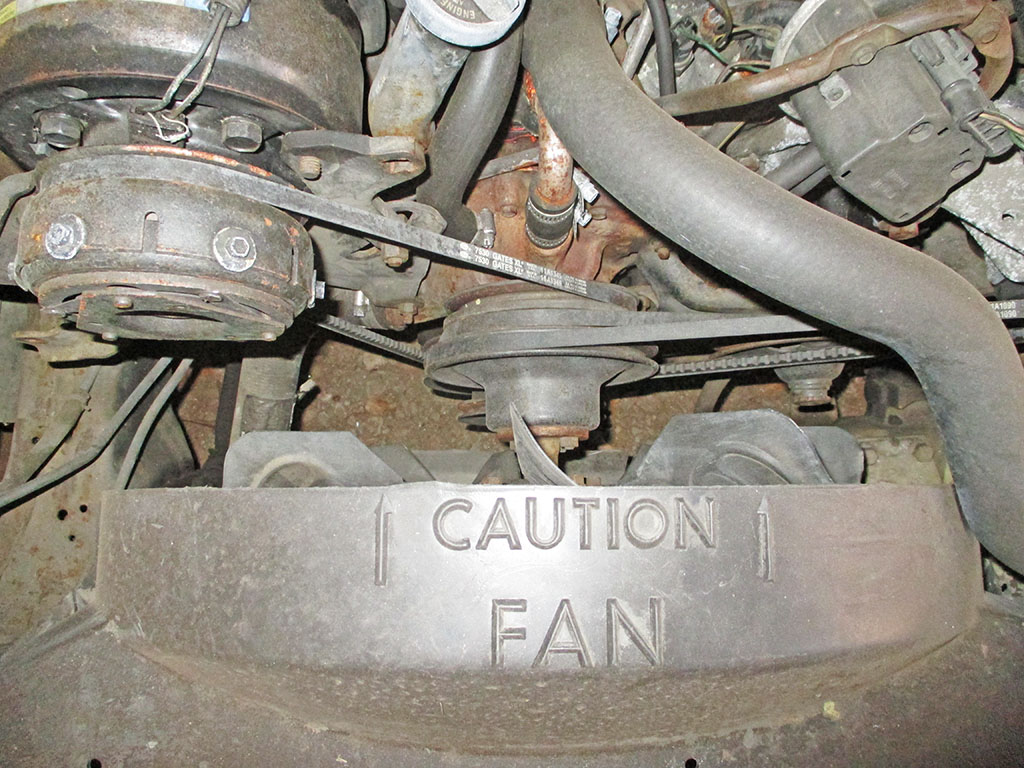
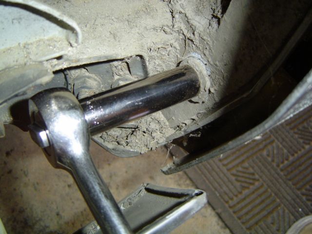
After much deliberation I decided the engine upgrade needed some additional upgrades if I wanted to get the most performance possible compared to the rated HP for the engine. Granted I'll never get close to an engine being run on a test stand with headers and no accessories bolted on, but each little bit helps. I didn't want the hassle/noise of headers on a Cadillac and modified cast iron exhaust manifolds were too expensive. So I'm going with reusing the exhaust manifolds off the 307 for now. Never being designed for duals from the factory, it became necessary to notch the transmission crossmember so the pipes can be tucked up like OEM. I'm sure Dad would surely consider this heresy by switching from single exhaust to a dual system but my goals are a bit different than his were.
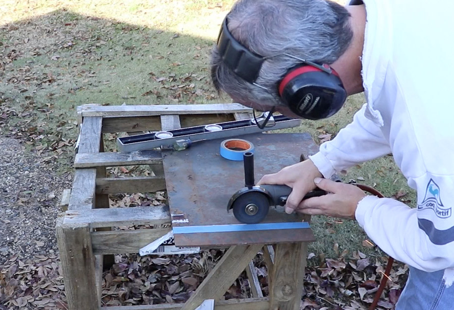
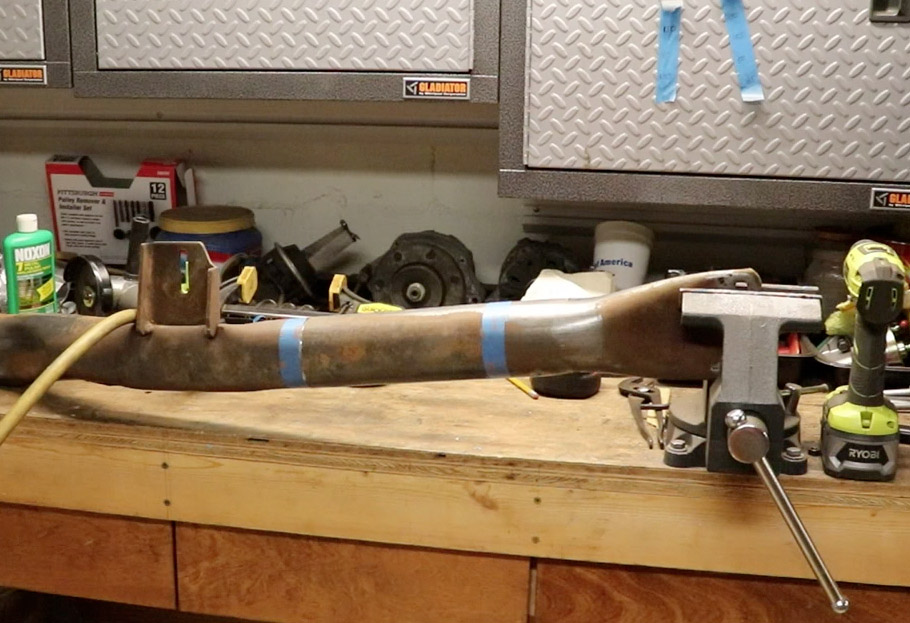
I lucked out by having a large 1/4 inch plate on hand (an old fireplace damper) from which to cut all my new pieces of steel. I haven't really worked with steel this thick before, so it was a challenge to get the sections I needed cut off of the large plate. My air grinder fell short due to the length of the hose I was using and my backup compressors lack of CFM output. But if I stop to fix my big compressor I'll never get this finished. I made a Harbor Freight run and came back with an electric angle grinder (and some cut off disks) to help me complete the project.
I started off by cutting a section of steel to fill in the width of what I had removed, intending to weld it in and then weld in some end caps on top of that plate. The OEM system was comprised of a single 2 1/4 inch pipe including the muffler and tailpipe. Since the cast iron exhaust manifolds measure 2 1/4 inches at the outlet, I decided to stick with that size, but doubling the capacity. The width of the notch is roughly 8 inches, so I'll have some wiggle room with the size pipe I'll be using.
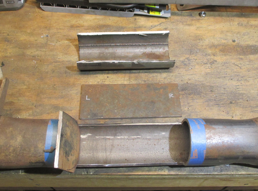
I first made a cardboard template of the shape of steel I needed. My XACTO knife came in real handy making all the tightly curved cuts. Once again the trial and error method proved my most valuable tool in getting the shape I would need dialed in.
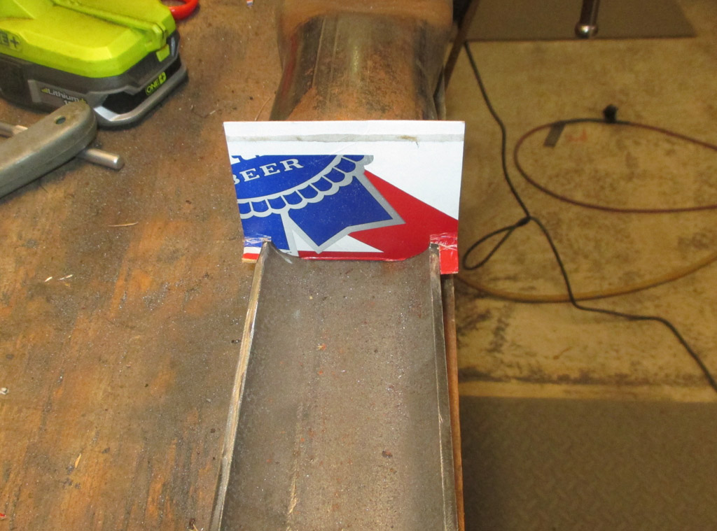
CARDBOARD TEMPLATE
STEEL END PLATE
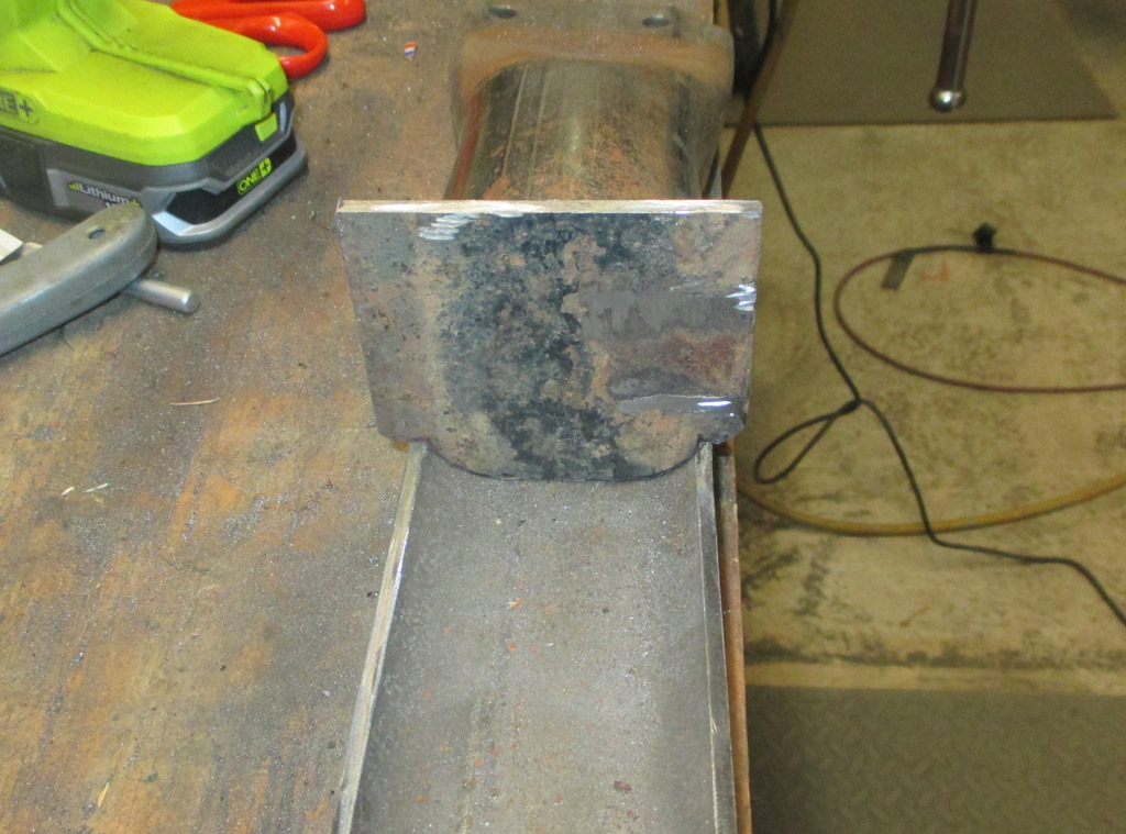
By laying the template on the steel, I traced around it with a fine tip sharpie marker. This gave me a guide to making my initial cuts on the steel. After that it was simply test fit, mark the high spot, grind down same. This part took quite a bit of time to get right.
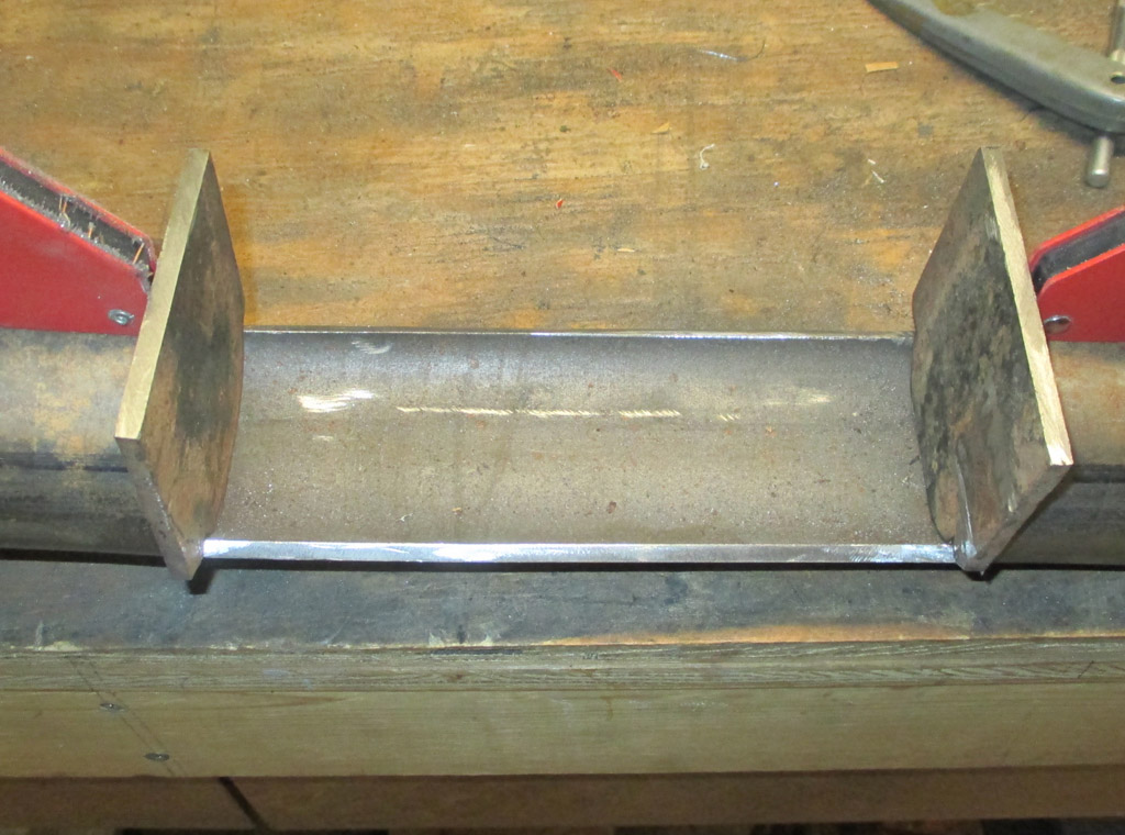
I changed my mind deciding to add strength by tying in the top section (bottom in the photo), to each side plate as well as the ends of the tube first. With the sides welded in I can add a short center spine between the end plates (to the height of the space between the crossmember top and my new plate), THEN weld the wide cap section on last. By doing it this way I hope to put back the strength I removed in cutting the crossmember.

Revival Plan (3/10/17)
After much deliberation, I slowly formulated a plan. I can rebuild it... I have the tools... To that end a heart transplant is in order. An LS swap would be ideal, but also a budget buster, time sponge, fabrication and wiring nightmare. No thanks.
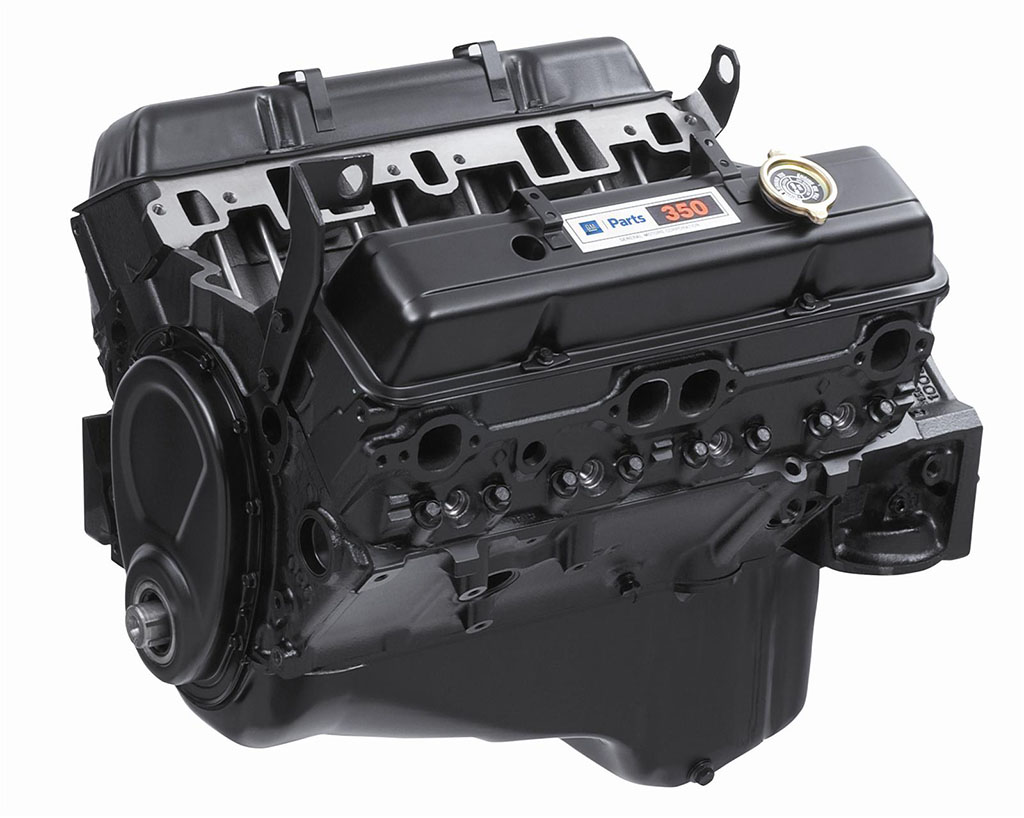
The easiest upgrade would be an Oldsmobile 350, 403 or 455 engine. I've read stories about the 403 being prone to overheating but a good motor for torque, which is essential to get this boat moving. I almost got an Olds 350, but the guy sold it out from under me. At least he called me and saved me a trip. I didn't want to feed a 455 (or a 472 or 500 cubic inch Caddy engine either), so my research continued. I can purchase a GM 350 (260hp/300lbs torque) for right around 1,500 bucks with a warranty. I've got an intake and several carbs on my shelf. I pulled the trigger.
Parked (5/8/14)
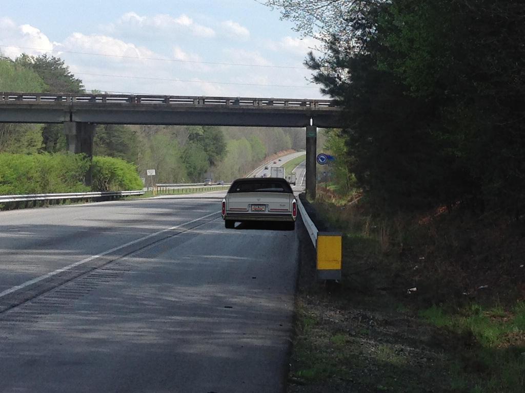
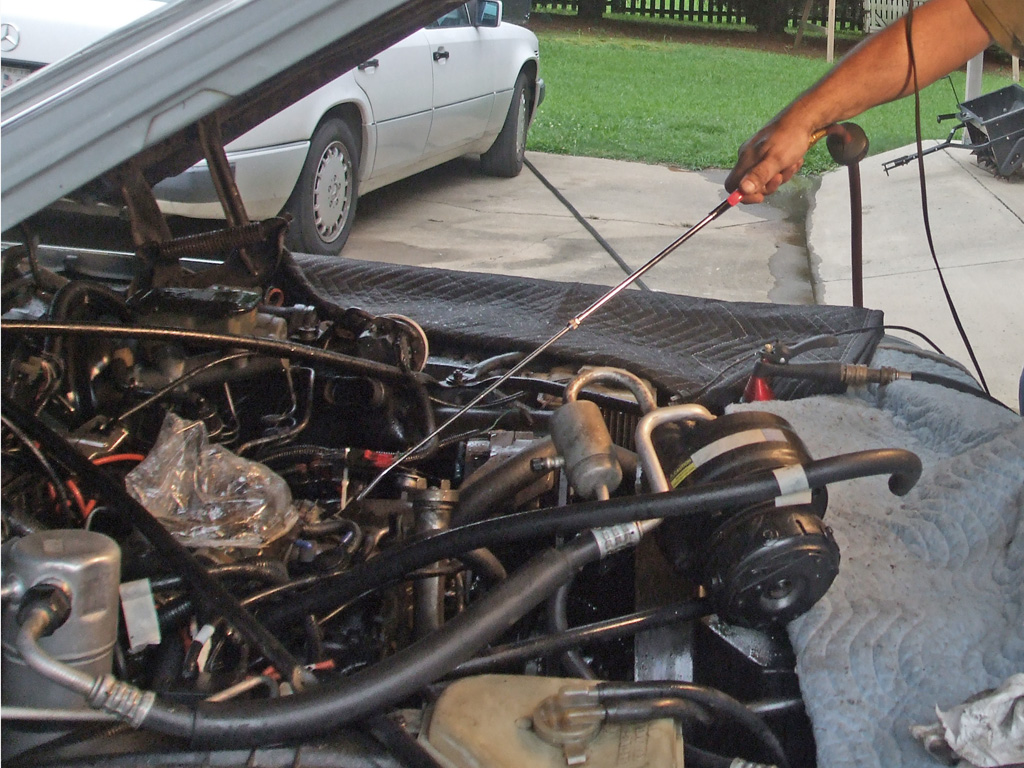
When Dad drove this car, he puttered around town locally on mostly flat terrain. I on the other hand, attempted to bring it up to daily driver status, so I could chauffeur Mom around to her various appointments because she likes how it rides. A rare combination of circumstances ground me to a halt on a beautiful day in May, when I attempted to take Mom to a doctor's appointment.
First there was this little issue with topography. Mom lives in the mountains, the interstate winding up a 6% grade for three miles before leveling off. The anemic 307 couldn't manage more than 50mph on the upgrade. A third of the way up, the red "ENGINE OVERHEAT" lit up, quickly followed by the "NO OIL PRESSURE" warning light. I pulled over and was greeted by plumes of steam as I raised the hood.
Not seeing an obvious leak I refilled the overflow bottle with 2 gallons of coolant (part of the emergency supplies I always carry), and waited for it to be sucked into the system. Two miles later I coasted into a truckstop, bought 2 more gallons and repeated the process. I tried going downhill with the heater blasting but overheated a third time. I threw in the towel and called a flatbed to haul me home. Pulling it into my driveway I heard a faint knocking sound. So, the motor's toast in addition to whatever caused the cooling problem in the first place. Perfect.
Cooling System
Intake Manifold Gasket Replacement (7/20/13)
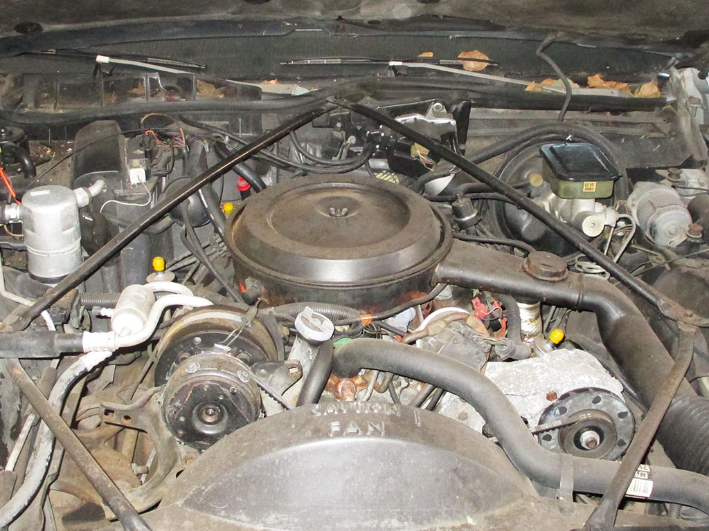
With no other viable option to stop my intermittant antifreeze leak, I bit the bullet and decided to remove the intake manifold. But before I can move forward with that, I need to actually get down to it. That means removing the air cleaner assembly and one at a time, removing each vacuum hose, labeling it and tucking it out of the way. Takes time up front, but saves headaches when the time comes to reconnect everything.
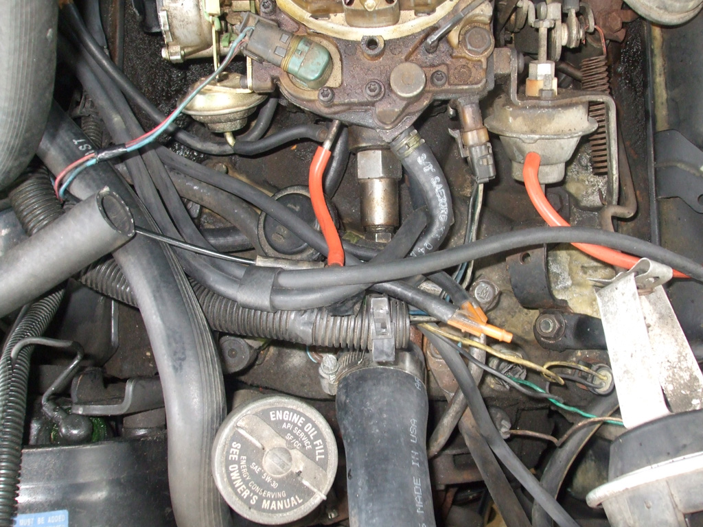
FRONT LINES

BACK LINES
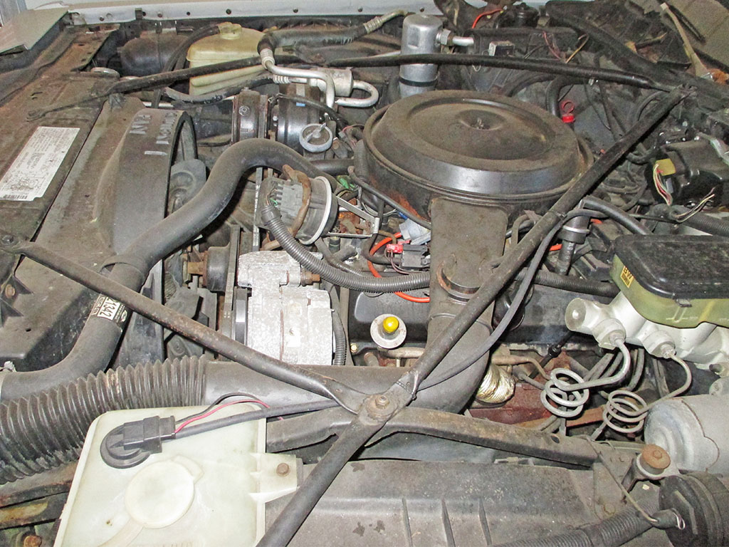
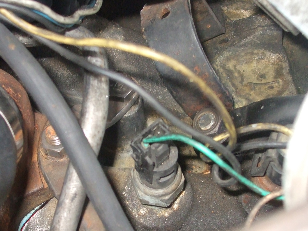
Of course, that's only part of the fun. Like many early emissions engines there's also half a dozen electrical connections to remove as well. At least with the electrical, each connecter is unique and will only attach to it's own connecter. Each also has some sort of indexing tab, so it will only go on one way. At least the factory did what it could to eliminate mistakes by those servicing the engine in the future.
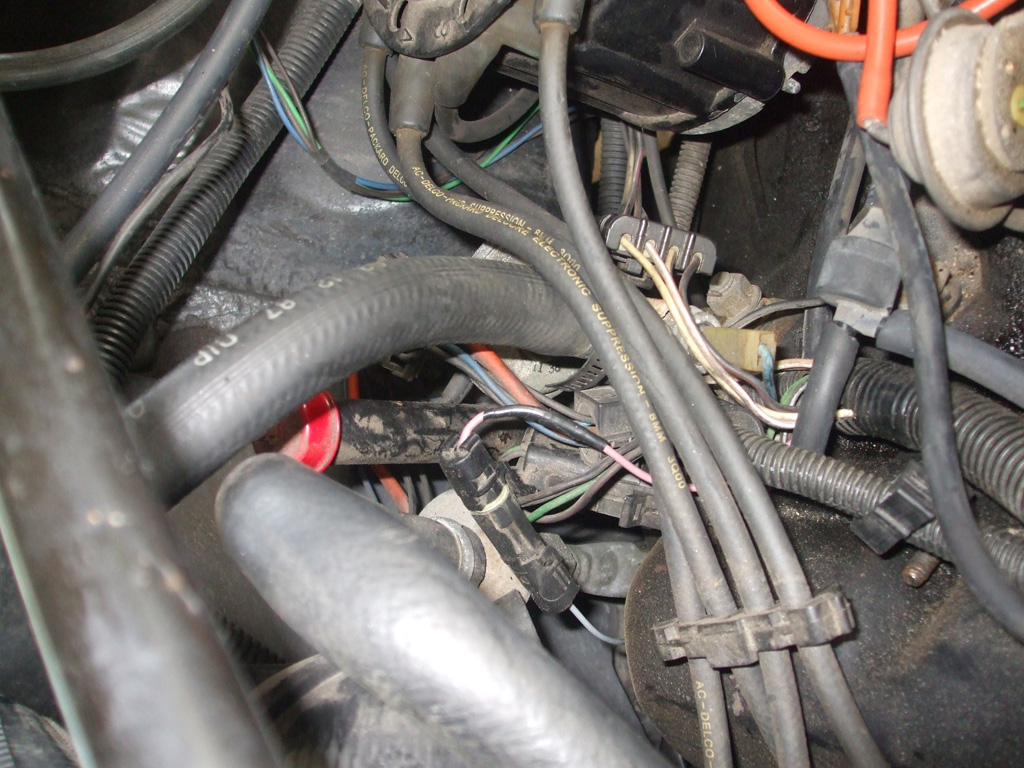
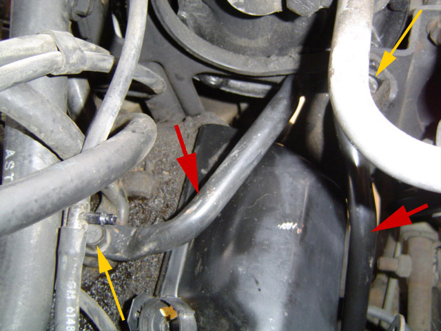
There's a real rat's nest of electrical connectors, not to mention heater hoses, the heater control valve and the transmission fluid dipstick located at the rear of the engine on the passenger side of the engine compartment. The tricky part here is to lean over the fender and carefully disconnect each connector and fold it out of the way... all without leaning on something fragile that will be damaged by having someone lean on it.
For the most part, there's enough slack to wire tie various wire looms up and out of the way to gain enough clearance to remove the intake manifold. At least with this engine I don't have to pull the distributor like I do on my Chevy engines. That saves me the hassle of marking the distributor and rotor in the hopes of dropping it back in at the exact spot it was removed from.
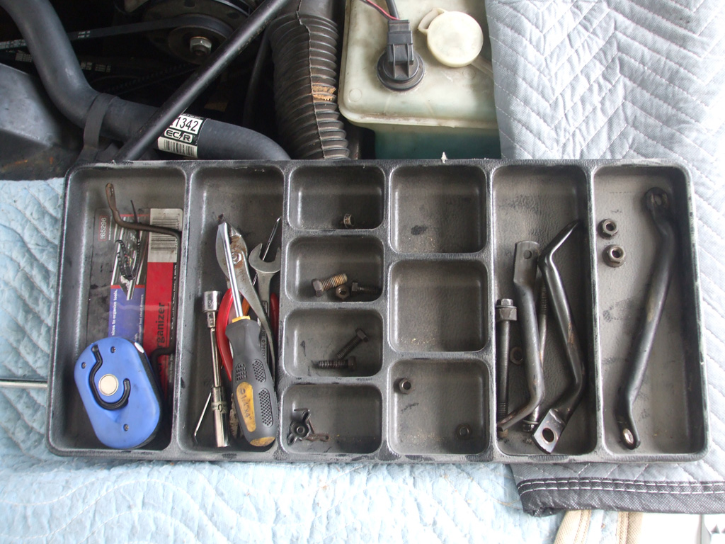
With a plethora of nuts, bolts, spacers and brackets to keep track of, "organized disassembly" is a must. Those tool drawer organizers sitting in your toolbox? Repurpose them when you're facing a project like this and you'll thank yourself when you begin reassembly.
If you don't have actual fender protecters laying around, old blankets or moving blankets will do very nicely to protect the paint of your ride as you tackle the job at hand. This shot was taken rather early in the disassembly process, as the tray filled up quickly.
With all of the hoses, brackets, cables and such folded back out of the way, it was time to lay down some engine degreaser in the hopes of making sure as little crud as possible gets into the engine once we lift this baby up and out of the way. For this we turned to good old Gunk brand engine degreaser. I've been using the stuff for years on any mechanical device that needs to be cleaned for maintainance or teardown. As a final preparation before spraying the engine degreaser, we capped off all the vacuum ports and put a plastic baggie over the carburetor.
A new technique here, is the use of compressed air to "blowdry" the engine. Every other time I'd either start the engine to burn off the rinse water (not possible in this situation), or (when used on my lawn equipment), let it air dry in whatever sunlight is available. This inefficient method wasn't an option with such a big job facing us. Compressed air and blowgun to the rescue!
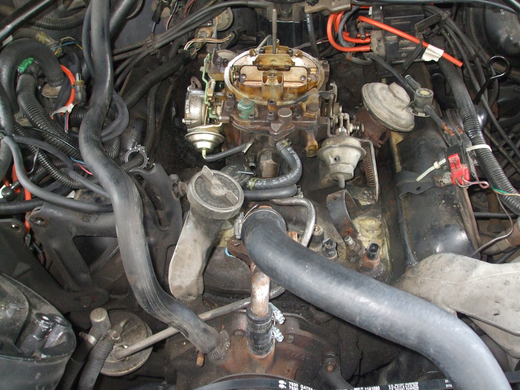
One final shot before yanking the intake. The A/C bracket to the left of the oil filler tube will be the last thing we have to get out of the way to facilitate removal. Of course we still have to remove the upper radiator hose, the fuel supply line and the water pump bypass hose and a few other odds and ends before liftoff.
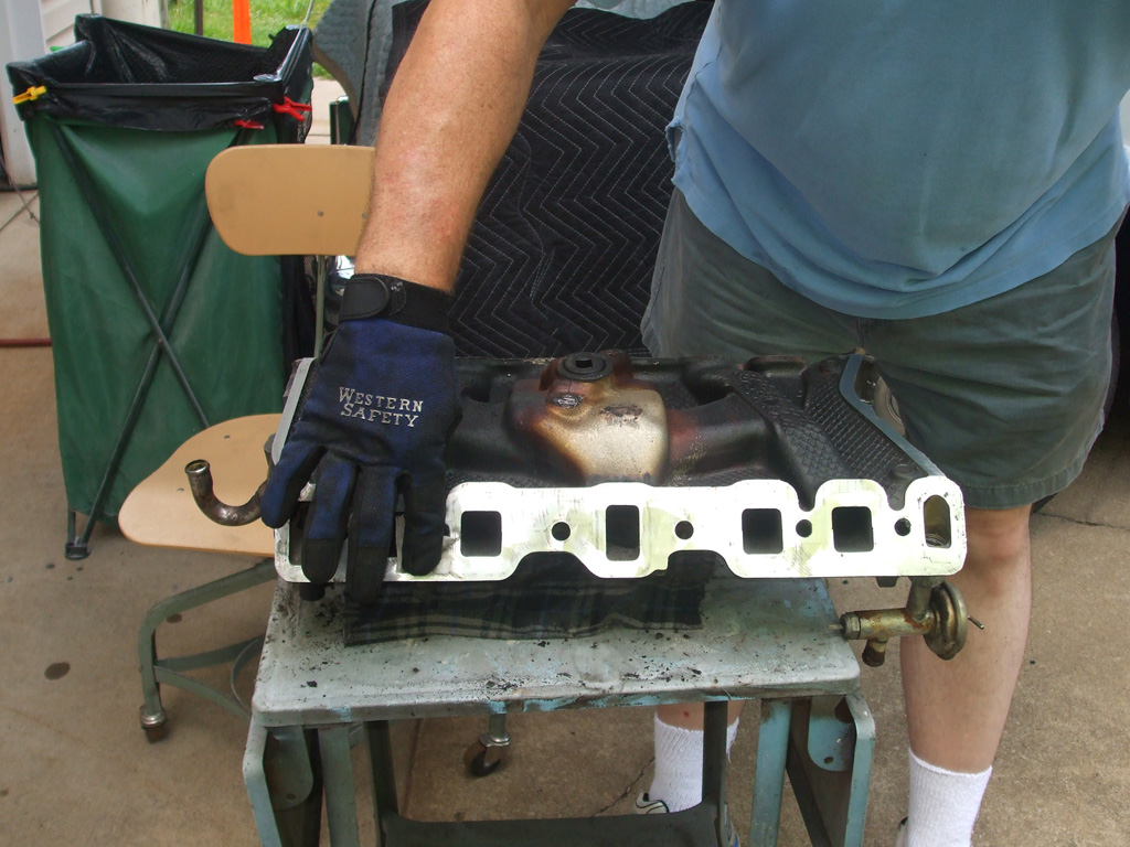
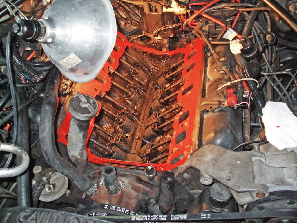
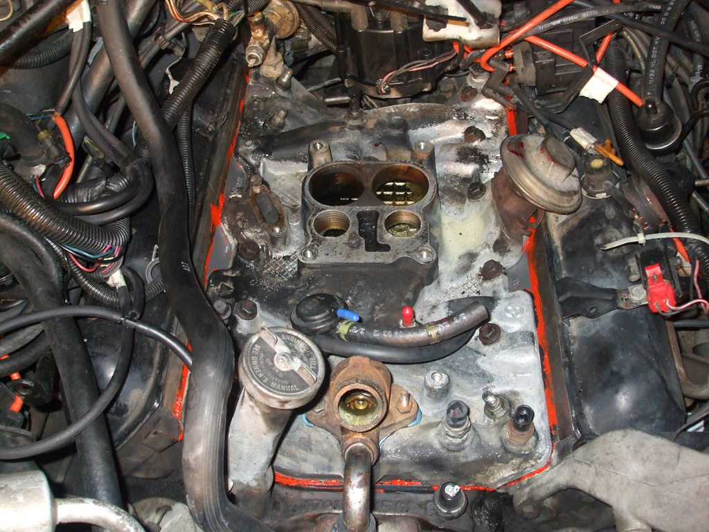
With all the intake manifold bolts removed, it was time to get out a pry bar and work it free of the heads. We didn't have to pry too hard though, the darned thing was evidently just sitting there it came free so easily. The fact that it was leaking oil like a torpedoed submarine probably didn't help matters any. At least the intake was aluminum, which made wrestling it up and out of the engine bay easier than if it had been cast iron.
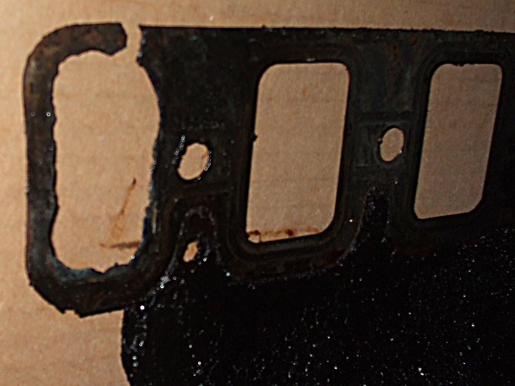
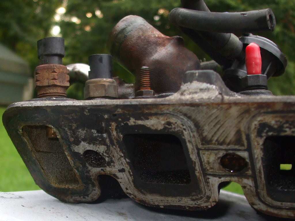
This particular engine (Oldsmobile 307 CID) has a combination valley pan and intake manifold gasket which will need replacement. According to my research on the internet, the gasket tends to fail just behind the alternator. Lucky me.
With no radiator pressure testing unit available, we used deductive reasoning. That and drilling down into the archives of sites like classicoldsmobile.com & cadillacforums.com where the steel "turkey tray" gasket seemed to be the culprit in many instances. After digesting the evidence, the logical decision was to remove the intake manifold, to fix this thing once and for all.

FRONT BLOWOUT
BACK GETTING READY
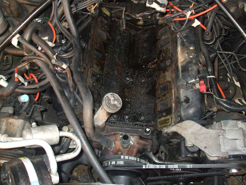
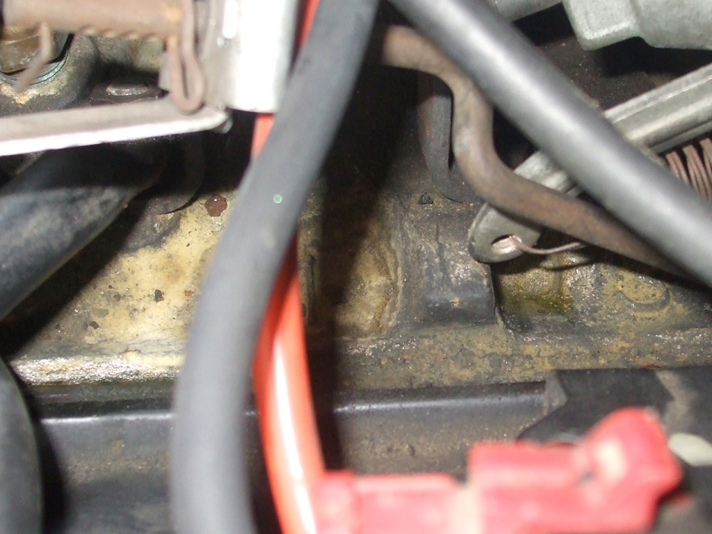
Sure enough as soon as we pulled the manifold, there was the evidence staring us in the face. At least one corner of the gasket was MIA probably due to corrosion by the looks of things. Not only had the front failed, but the rear water passage on the same side was doing a number on the gasket there too. Vindicated that the correct diagnosis had been made, it was time to grab some lunch and make a parts run.
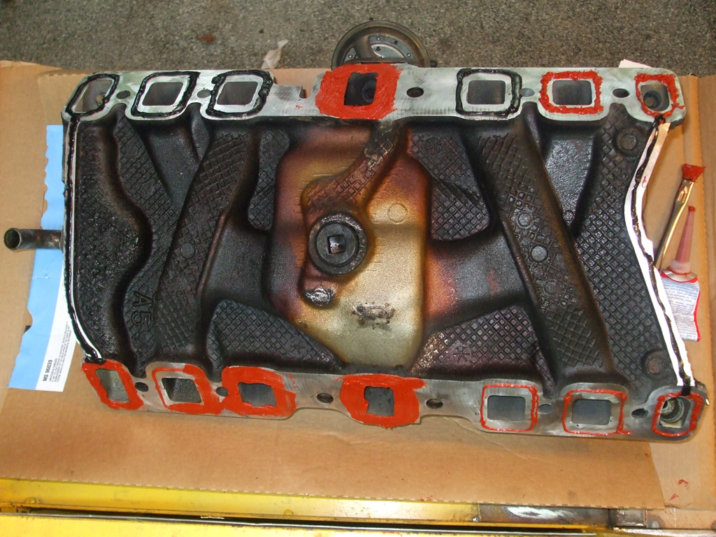
Judging from the marks on the intake manifold (seen here soaking in yet another hosing down with engine degreaser), this leak had been going on for quite some time. With as little and infrequent driving as I did for Dad, I'd noticed the antifreeze level going down, but there was never a puddle under the car. By the time the car came into my posession, things had deteriorated significantly and, well, there you go. Mystery solved.
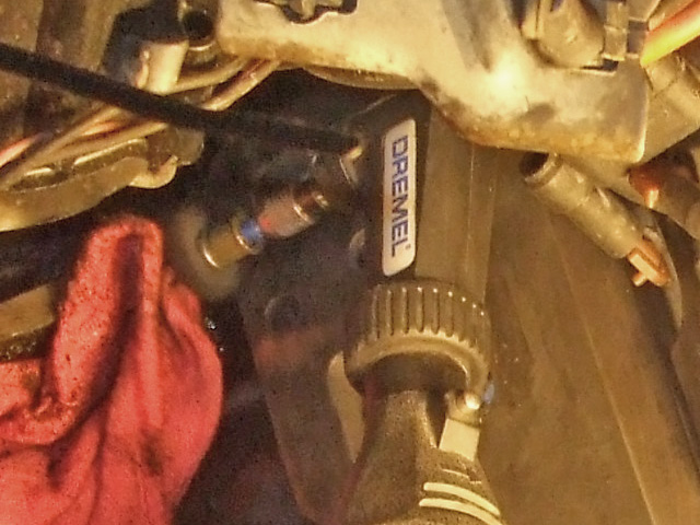
While the manifold soaked, it was a good time to use a 3" conditioning pad in the 90* die grinder to remove the old gasket material. By the time I'd worked my way to the back of the engine, things got too tight to use the die grinder. Once again, Dremel (equipped with its own mini conditioning wheel) was there to save the day.
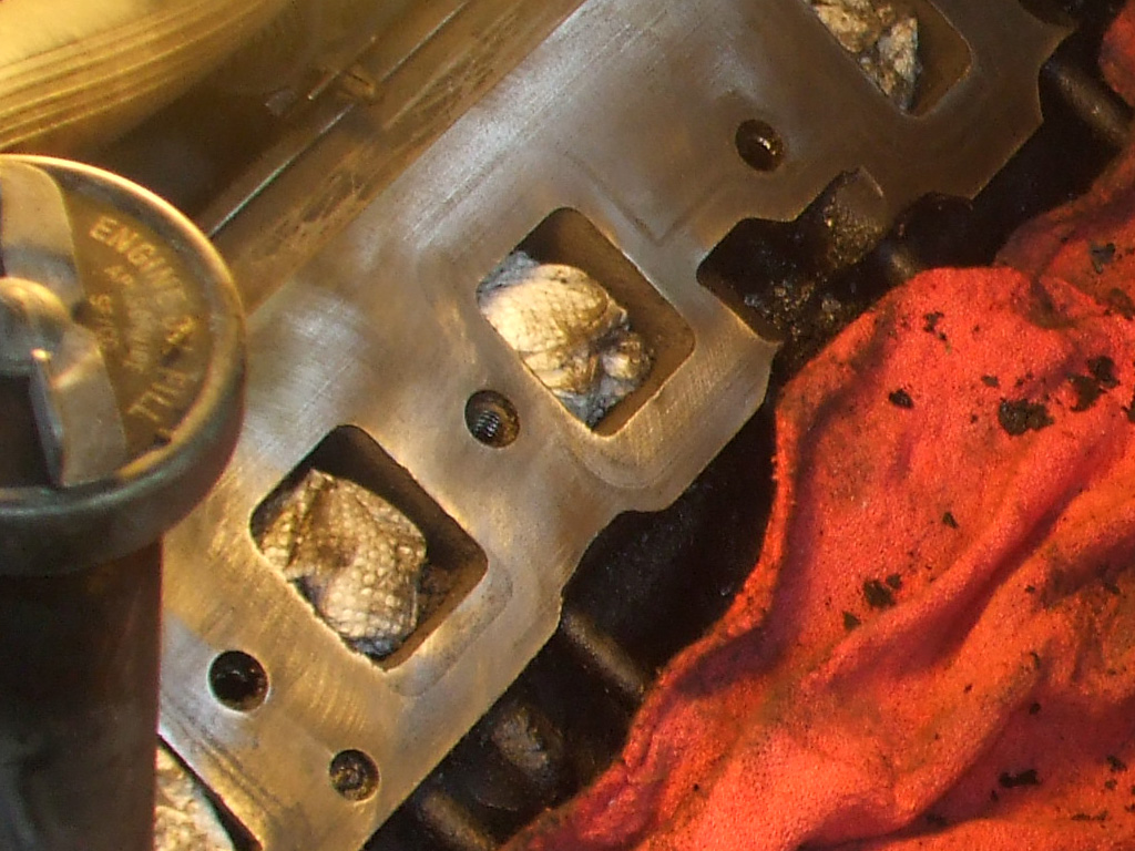
With all the gasket material removed through physical means, it was time to clean the surfaces for the next step. That meant paper towels cut up into 4" squares that can be turned to a clean edge when used. Used with what?. Why... good old disk brake cleaner of course. For bare metal or machined surfaces, this is my go-to for final cleanup before final assembly. Not recommended for painted surfaces though.
As we did with the heads, we used the same conditioning disk to remove old gasket material, oil and antifreeze stains. By selecting a fine (non-agressive) disk, we're able to clean the mating surfaces without removing any aluminum. Once again, final cleanup was accomplished with paper towels and brake cleaner.
With all the surfaces as clean as we could make them, it was time to apply some red high temp. silicone gasket material. A 1" wide acid brush (bristles cut short for stiffness), made it easier to spread the silicone evenly over all the sealing surfaces.
The front and rear rubber seals were laid in a bead of silicone, with another layer on top of each end gasket. This way we're not relying on the rubber alone. The rubber now serves to hold the silicone in place and the silicone does the sealing. The original rubber seals were so brittle they snapped off in chunks. Hopefully our method will be longer lasting than the originals.
Once we removed the paper towels we'd used to keep crap out of the manifold ports and folded up the rags we used to collect the remaining oily blobs of gunk in the valley, I used the shop vac to make a final pass to collect what the rags had missed.
While we waited for the silicone on the heads to skin over, we used a narrow tip to apply a small bead around each port opening on the head side of the valley pan. By the time we'd done that it was time to bed the "turkey tray" down into the red goo.
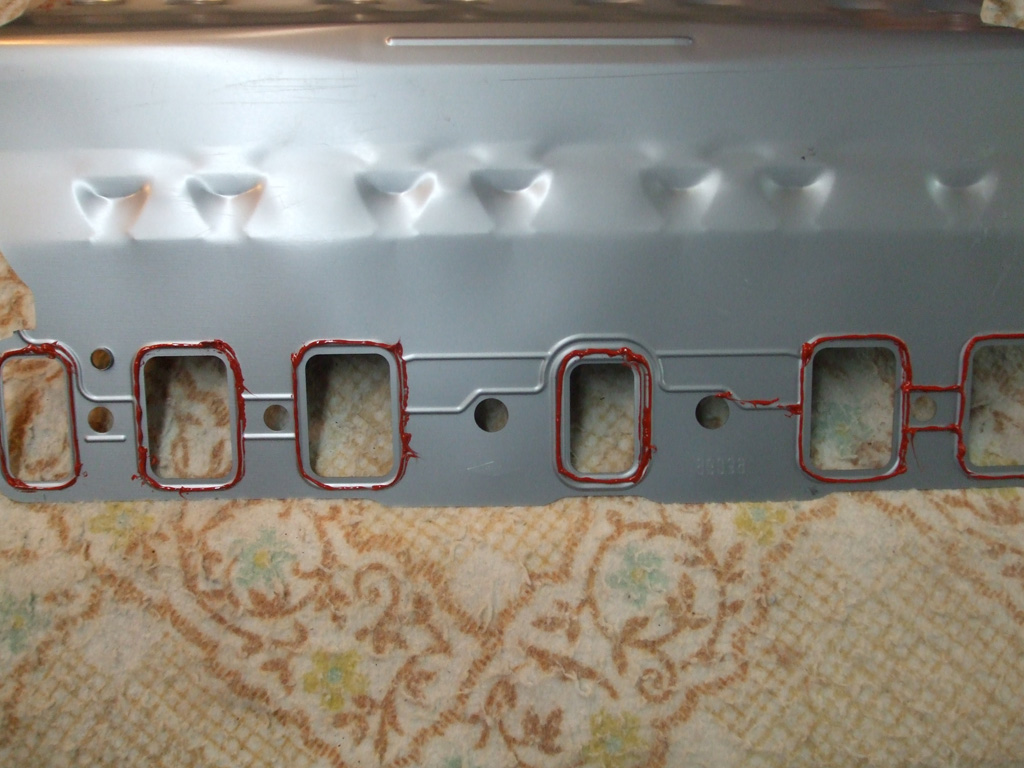
PAN PREPPED
BEDDED IN
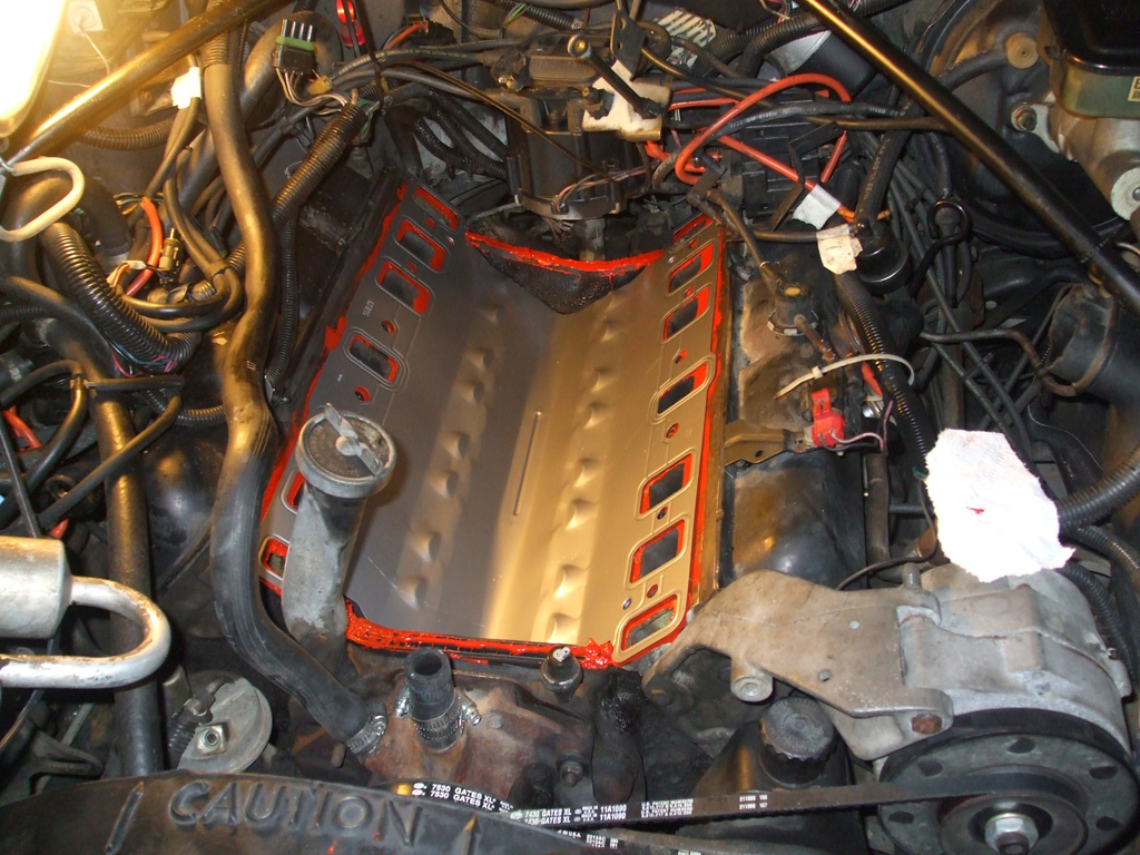
The pan had to be bent slightly into a sharper V shape (probably flattened a bit to make boxing easier), in order to fit properly. Then we pressed the pan down into the silicone. Next up... the manifold itself gets the same treatment.
As we did with the heads, and the pan, we used the same approach on the manifold itself. This time we finally ran out of the high temp red silicone and had to switch to the black RTV silicone that came with the valley pan. Roughly the diameter of my pinky, there's no way we'd have had enough for the whole job. If I had thought we'd need two tubes of the red, I'd have bought two. No matter though, the job got done with what we had on hand.
It took awhile to get the bolts lined up, but after some finessing with a small pry bar we were finally able to get all the bolts started by hand. Then we ran the bolts in snug with a ratchet before moving up to a torque wrench. Each bolt was torqued to 15 foot pounds, 30 foot pounds and finally the 40 foot pounds the book called for. With that accomplished, it was time for another progress picture.
We cleaned up the carburetor and manifold mounting surfaces, installed a new carburetor mounting gasket and torqued the bolts to 15 foot pounds. Then we began the rather tedious task of reconnecting all the vacuum hoses, electrical connectors, replaced the heater core hoses, tightened the belts, filled the radiator and reconnected the gas pedal cable, cruise control rod and TVS cable.
Finally the moment of truth had arrived... it was time for a test. It took a bit of cranking before the bowl in the carb to filled with enough gas for the engine to fire, but it did. Ran real rough for several minutes, but revving it slightly made everything smooth out eventually idling as smooth as it had before the operation.
We let it get up to operating temperature, topped off the radiator and checked for leaks. Finding none, we decided to break for lunch.
After lunch, we stopped to pick up a 5 quart jug of oil and a new oil filter. Since we'd had all the passages in the head open, it was highly likely that some antifreeze had leaked down into the oil pan. When taken in conjunction with the great unknown of the last oil change date, this became a no-brainer. By the time we returned from lunch the engine had cooled enough to change the oil.
This session finally resulted in stopping the antifreeze leak that had been plaguing me for some time. I tested the car out going back and forth to work (20 mile trip - one way), and the car performed quite well with no further leaks. However the roads I was travelling were comprised of primarily flat terrain, with only two small hills that were easily traversed. The real test would be travelling to NC up a steep 5 mile grade to take my Mom to her doctor's appointment.
Coolant Leaks - Round 1 (7/1/13)
I pulled into my driveway (just after filling up the tank) and decided to check my oil, just to make sure everything was up to snuff before taking a trip out of town. Yeah... good thing I did. As soon as I popped the hood, I could see antifreeze all over the left side of the intake manifold. When I checked the overflow bottle I'd topped off the day before and found it empty, the message was loud and clear.
Houston... we have a problem.
Some folks may be able to pull a car out of mothballs and run it with no issues for years. They've got a certain lucky streak or mojo working for them. I am not one of those people. Usually (my van is a perfect example) when I get a new vehicle (new to me that is), there are certain things I do like install new belts & hoses to prevent problems like this. What happened? Simple really. I was pressed for time and ignored my own vehicular mantra. So much for shortcuts.
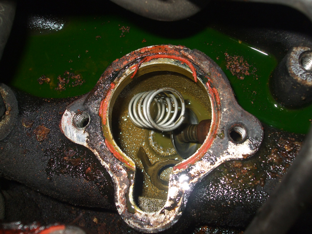
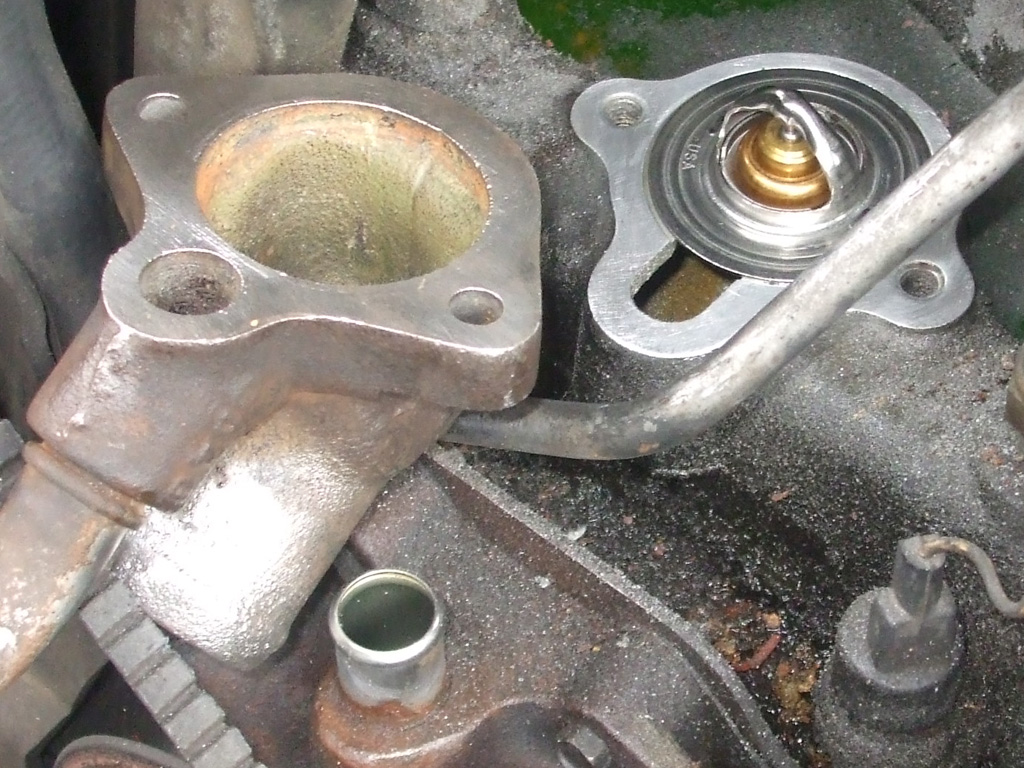
At first, I thought the upper radiator hose or one of the heater hoses had let go, but I felt all over and couldn't find the source of the leak. The upper radiator hose was curling away from the thermostat housing, so I figured I'd replace the hose, clean everything up and I'd solve the problem.
And... if I'm going in that deep, I may as well replace the thermostat since there's no telling when that had last been done either. I'm glad I did. I've been tinkering with cars for a good many years now, and this is the first time I've ever seen anything like this.
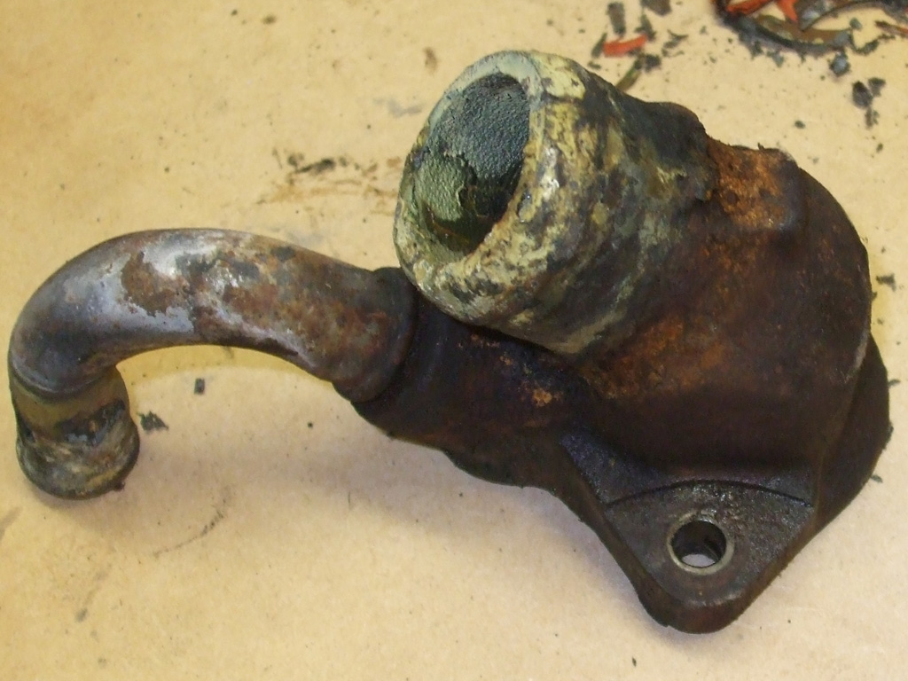
With the upper radiator hose off (as stiff and brittle a hose as any I've ever dealt with), I could begin the cleaning and reassembly process. Not only was the hose stiff, but there was an insane amount of buildup on the thermostat housing. This just won't do. Before I can replace the worn out parts with the new ones I'd purchased, I had to get everything nice and clean.
There's a method to my madness here. Once I get everything all cleaned up, I'll be better able to tell if there's any damage hiding underneath all the grunge. I was operating under the assumption that my situation was the result of a "pressure leak" but there could be a crack hiding underneath all the crap. I chucked a wire wheel into my electric drill and went to work. This produced a truly vile smelling cloud of dust, so I set up a small electric fan nearby to blow the dust out of the way.
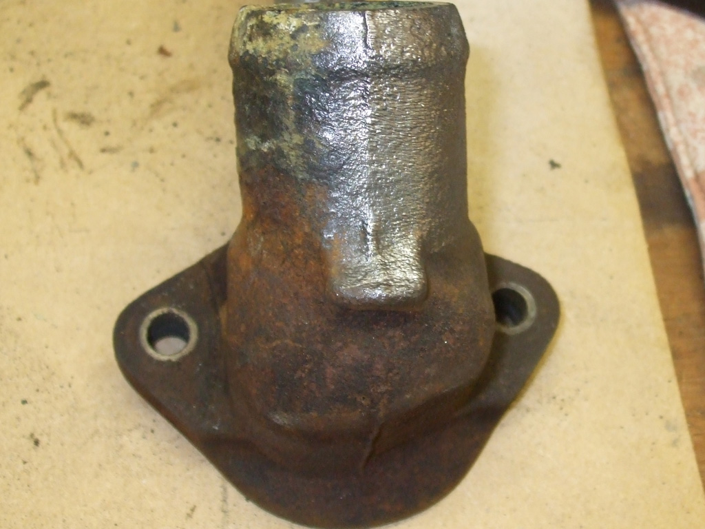
At the halfway point I took a break to blow my nose (the fan wasn't the best dust control solution after all), and things were looking pretty good. At least there were no cracks visible, which meant this would be a straight forward refurbish and replacement job, thank heavens.
At first, my primary objective had been to replace the upper radiator hose and thermostat so I could have wheels again. But then I started thinking. Right? I've got some time off and some money available... may as well get the lower radiator hose too, because if I don't sure as god made little green apples it would be the next thing to fail on this boat. This meant a trip to my local independant auto parts store which stocks Gates belts and hoses, a brand I've trusted since I had my '69 Chevy.
"When you're up to your rear end in alligators, it's difficult to remind yourself that your initial objective was to drain the swamp." - Ray's Garage

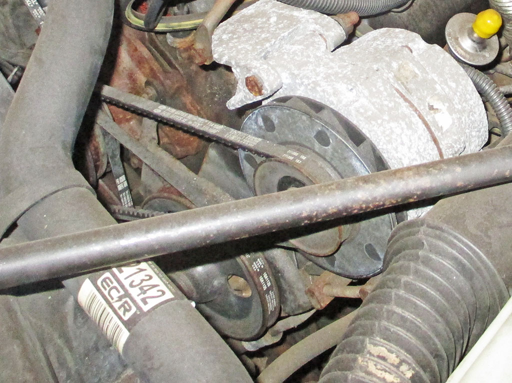
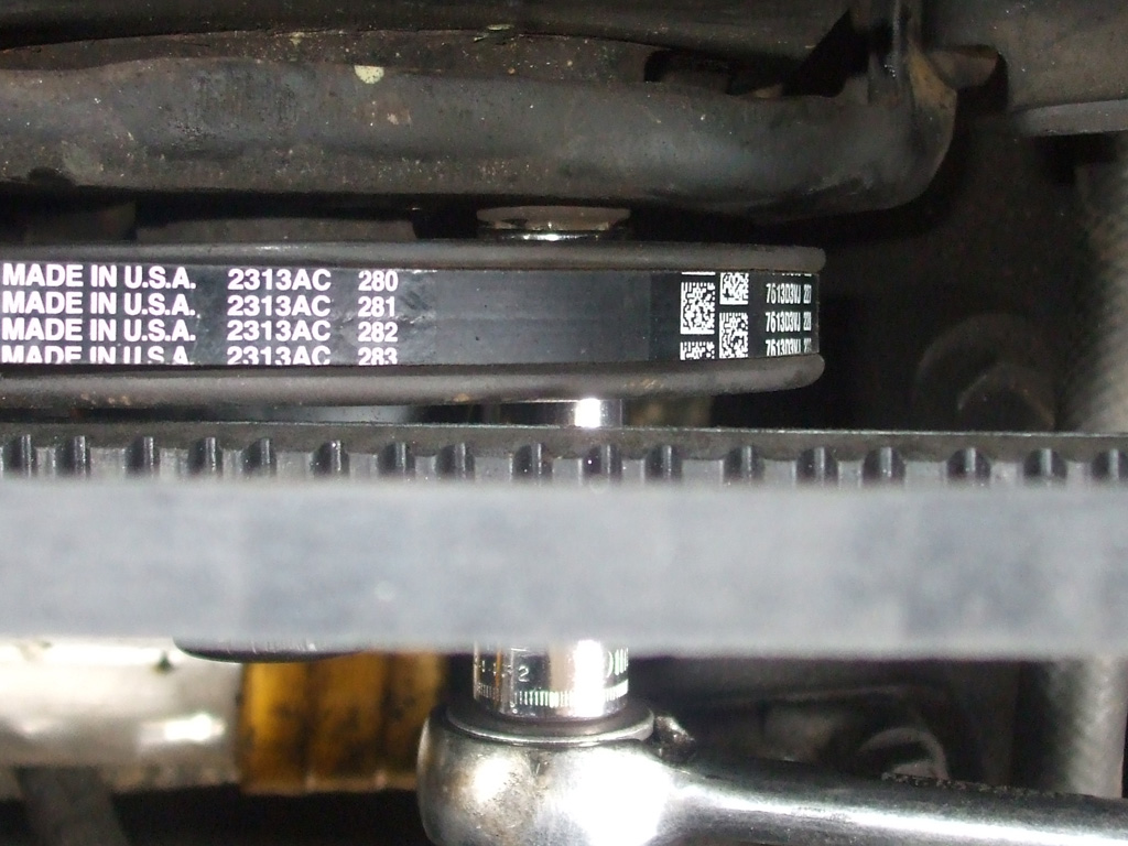
With my initial objective requiring a trip to the parts store, I noticed another issue. Crap. No sense ignoring it. Gotta replace this too. And it stands to reason that if one belt is in this condition, chances are the others are getting ready (although they did not show signs of it), to fail as well. So, my shopping list for the auto parts store just quadrupled, 'cause this baby's got 4 separate V-belts. Ah my old friend the snowball effect... how I've missed you.
Of course this is the natural effect of time on the rubber expendable items found under the hood of any car, new or old. Dad kept the Caddy garaged, but had not driven it on a daily basis in quite awhile. Since I plan on this being my Daily Driver for the forseeable future, I've got to make it dependable. That means some preventative maintenance while I've got the time... as my van project (which I'd planned on using my time off to work on), languishes in my carport.
There, that's better. Took me about 30 minutes to get to this point. All that remains at this point is to give the mounting surface of the intake manifold the same treatment. Then all I've got to do is drop in the new thermostat (Stant 180* made in USA believe it or not), paint my new Felpro gasket with gasket adhesive/sealer and button it all up again.
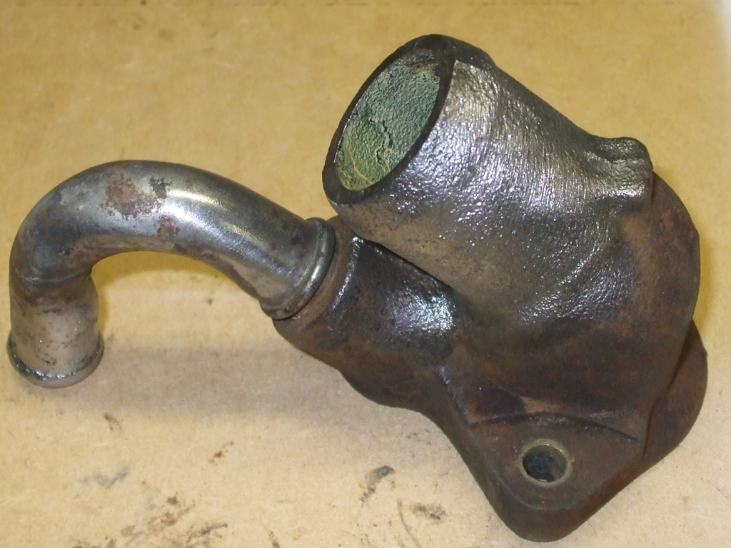
HOSE MOUNTS
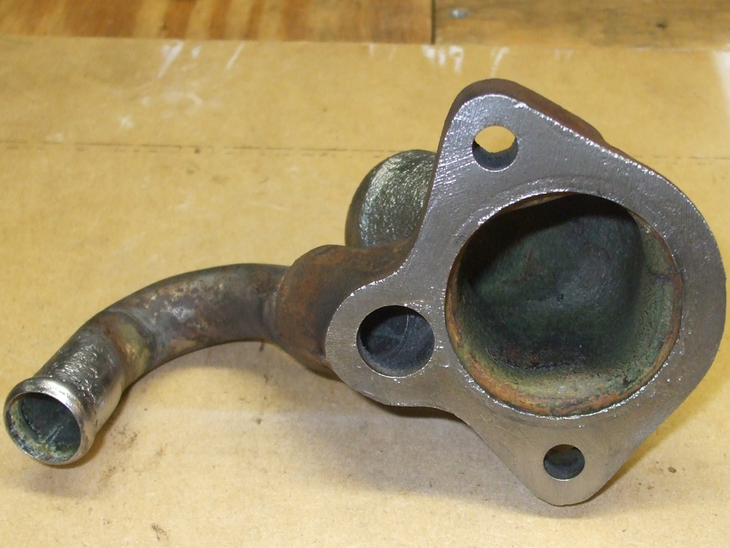
GASKET SURFACE
Sounds real simple. This particular engine has a unique bypass hose that connects directly to the water pump. So I have to line both things up at the same time and then start the bolt and stud that hold the thermostat neck to the intake. I measured the old hose and cut a new one to the same length, which somehow turned out to be too long. I whacked off about 1/4 inch and everything lined up as it was supposed to.
With everything rolling along I found the time to take a break and snap a few pics. The only thing missing in this shot (which was busy drying on my workbench), is the thermostat housing gasket and the adhesive I used.
Available at any local parts house, I grabbed a bottle of Permatex gasket adhesive/sealer that I feel gives an extra measure of security in assembling various gasket-sealable surfaces. When you're into a project this deep, it pays to lay down the cash for qualiy adhesives. This stuff is great for valve cover gaskets too, keeps them in place as you thread the cover into place between all the hoses and wires under here.
So, my approach here was to use a 2" surface preparation disk (think 3M paint removal disk and you'll come close), on my electric drill (couldn't see dragging out the air compressor, hoses, die grinder etc.), at low RPM's to prepare all gasket surfaces for proper assembly. A quick wipe with brake cleaner (just to make sure everything was spotless) and all systmes were go for reassembly.
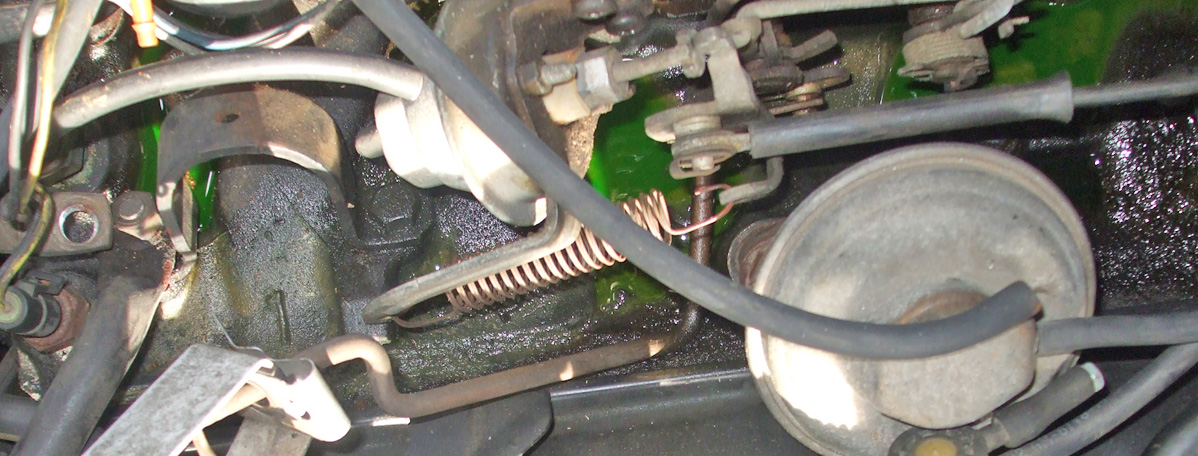
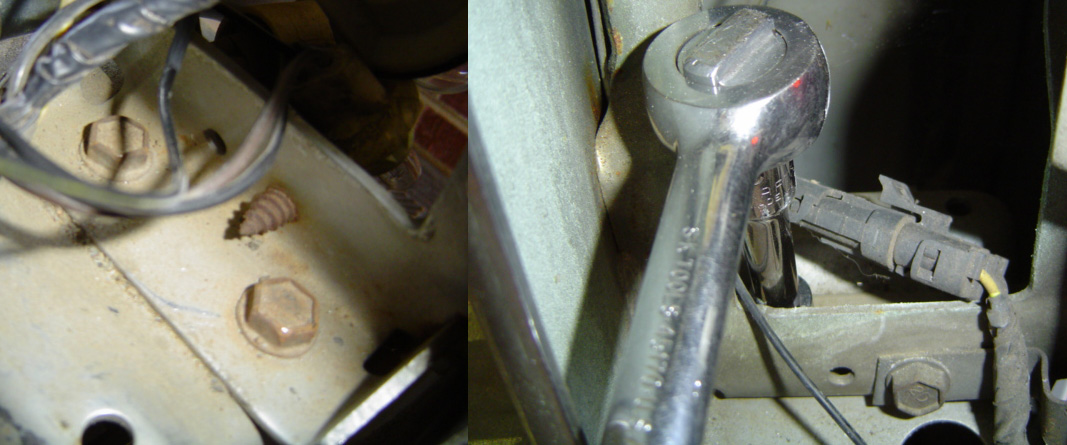
When I started out, I had this feeling of competance. Replace a power steering pump belt? I can do that blindfolded... or... perhaps not. Somewhere around the 3 hour mark (any and all sense of competance seemingly evaporated into the atmosphere), I had completely removed the power steering pump, replaced the belt and re-installed the pump... only to find I was no closer to adjusting the belt properly than I'd been hours earlier! Even with every bolt holding the thing to the engine sitting in my socket tray, I couldn't find the one (which eventually turned out to be two) bolt that would let me pivot the pump! I degreaseed my hands and hopped on the interwebs to find the path to my salvation.
ADJUSTMENT BOLT TOP
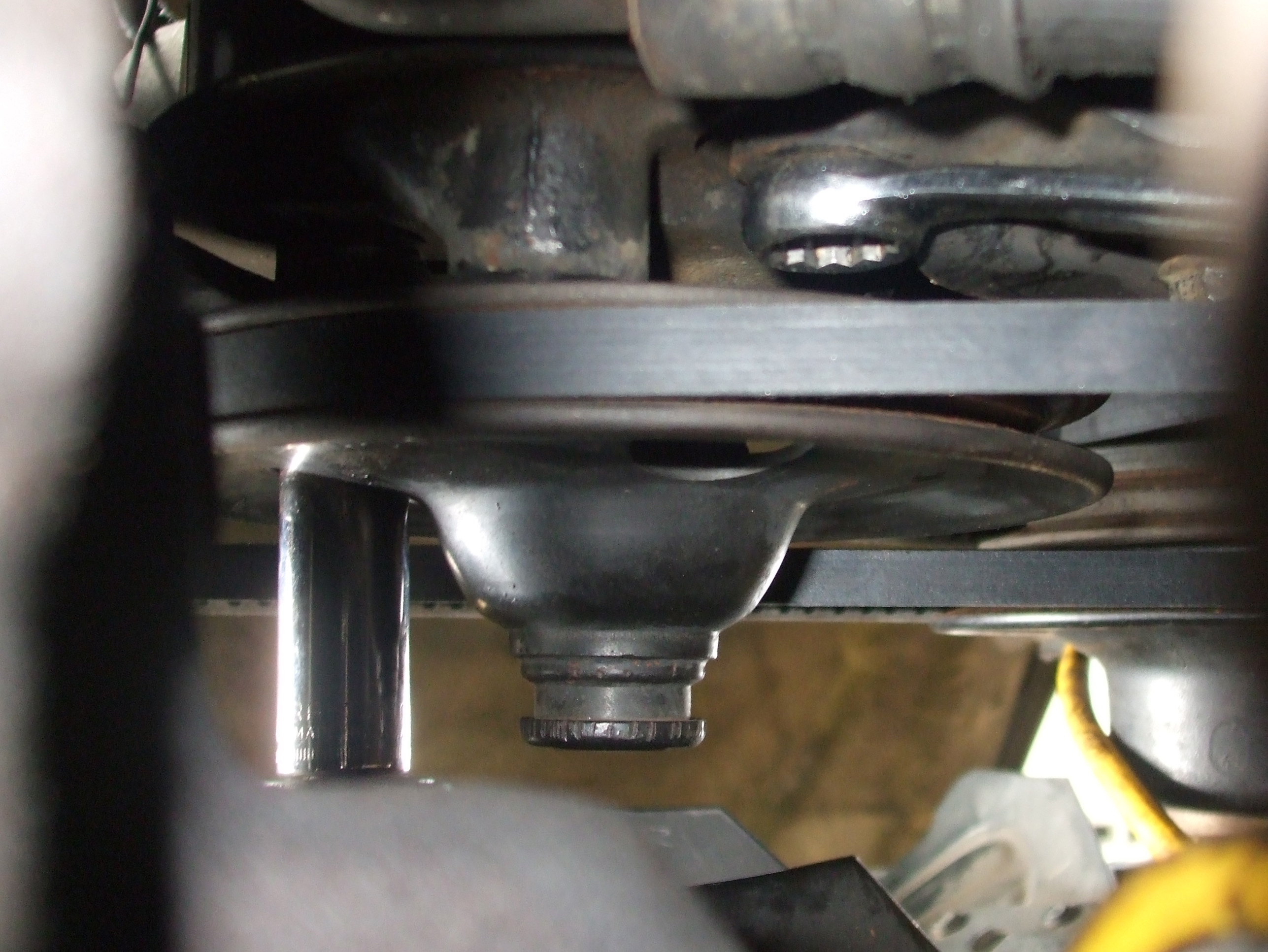
PIVOT BOLT BOTTOM
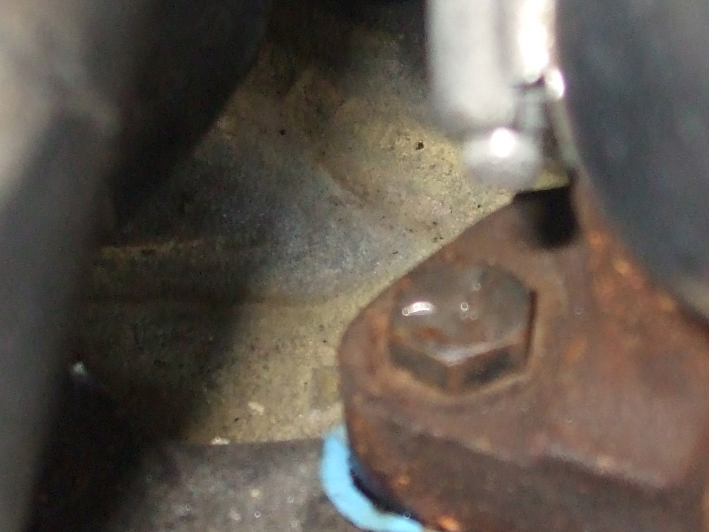
When I first dove into this, I'd noticed three holes in the pulley that spins the power steering pump. Hmm, that's a rather interesting design... now why do you suppose the factory would design something like that? Maybe so one of the holes can be used to access the "missing" adjustment bolt? Even that wasn't the entire solution though. You have to crawl underneath and loosen the 15mm bolt partially hidden behind the high pressure hose, in a stamped recess of the power steering pump bracket. The instant I loosened this bolt, the pump slid to the right, which was what I'd been striving for all along. What a friggin' nightmare!
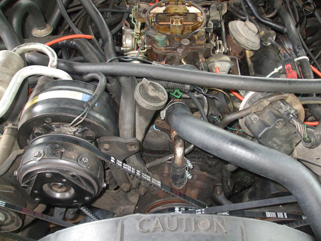
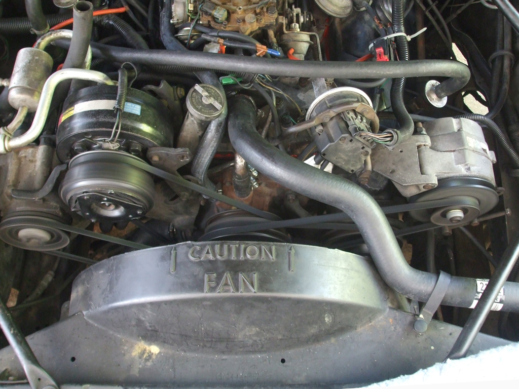
With everything in place and adjusted to my satisfaction it was time to snap a picture of the finished product. The final total: 4 new belts, two new radiator hoses, one new thermostat (and gasket) and uncounted vaccuum hoses replaced. New air filter and fuel filter installed, all fittings tightened and carburetor mounting bolts tightened.
On a personal level, 4 vacation days (wherin it poured down rain, just for grins), shot to hell. Two busted fingernails, three skinned knuckles, multiple abrasions (thank you Mr. Fan Shroud) to right arm and... one particularly painful drop-light BURN to the inner forearm! Three destroyed T-Shirts, two soiled pairs of walking-shorts (external, not internal) and an intense hatred for whatever engineer dreamed up this nightmarish system of belt adjusters.
So, this friends and countrymen is how you replace belts, hoses and filters on your basic late 80's Oldsmobile 307 V8. Yes, this vintage Caddy was actually Olds powered. Hopefully this has placed me ahead of the curve for some of the more typical failure points on this vintage of automobile.
Epilogue. After a 100 mile round trip (including some rather steep mountain roads requiring frequent downshifts into "passing gear"), I simply couldn't resist taking a look under the hood. The day before, I'd noticed a small leak and tightened the thermostat neck clamp in a desperate attempt to stave off replacement of the intake manifold gasket.
LEFT FRONT
RIGHT FRONT
SIDE VIEW
It's going to take awhile before I gain enough confidence in this machine so that each errand I run will not end up as mad dash for home for some sort of emergency fix. Time will tell I suppose. Until then, I keep the trunk stocked with antifreeze, oil, funnels, rags and tools. You know... just in case. Did I mention I bought a new set of spark plugs for this baby too? Yep. Sure did. They quietly mock me from the shelf over my workbench where they've been sitting since I bought all the other parts.
DESPITE MY BEST EFFORTS... THE PROBLEM CONTINUES! I popped the hood yesterday to check the oil, since the car does use some. When I reached for the dipstick I saw antifreeze all over the intake manifold. Again. WTF??? ARE YOU KIDDING ME? To preserve what little sanity I have left at this point, I've sidelined the damned thing until such time as I can diagnose just WTH is going on!
Bodywork
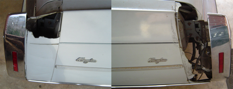
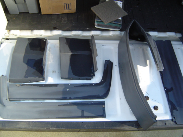
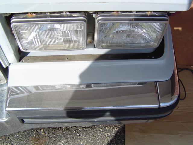
Since I typically have half a dozen or so little side projects going at any one time, the winter hours offer some much needed catch up time. One such side project is replacing the flexible (rubber?) bumper extensions on my Dad's '87 Caddy. When I made my initial order of new aftermarket pieces I neglected to order one particular piece I initially thought salvagable. So this necesitated a re-order (from a different aftermarket vendor no less), leaving me with one black primered piece along with all my previously completed ones. So the first order of business was to spray the new piece so I can get that project out of my hair. Of course I'd be a lot further along if I wasn't so anal retentive in wanting to take care of all aspects of a given project.
Fender Extension Replacement - Day 1 (10/17/09)
Case study...my Dad's '87 Caddy. For some strange reason, all Caddys of this era have the same problem. The flexible bumper extensions between the sheet metal of the body and the bumper deteriorate rapidly after a certain length of time. Doesn't seem to matter if the car's been garaged its whole life or not. My Dad's solution? Duck tape and lots of it! Now I'm as much a fan of the stuff as the next man, but when it comes to my ride, the words "astheticaly pleasing" take priority.
My solution was a wee bit different. I decided to tap the aftermarket. Since this problem is so widespread, there had to be a vendor somewhere with a solution (in fact there were several), most touting ABS plastic as the definative solution to the problem. GM designed the parts to be flexible, allowing the federally mandated 5-mph bumpers to compress and rebound. The only problem seems to be one of durability. These parts are (naturally), no longer available through GM. Not sure I'd want a set of NOS (new old stock) parts anyway, they may have gotten brittle just sitting on the shelf. The thriving after market parts seem to be more durable. Time will tell I guess.
So I ordered a set (this particular vendor was painfully slow in shipping, hence no names will be mentioned) and waited. That's the problem with vendors you find on line, some are reputable, others, not so much. Vendor #1 gave me a song-and-dance about being on vacation, backordered parts etc. Bottom line...send me a frickin' email an let me know what's going on. How hard is that?
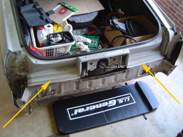
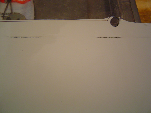
Here's a shot of the rear quarter panel extensions, or "fins" which were in the worst shape. The passenger side was riddled with cracks, while the driver's side was pretty much MIA (missing in action).
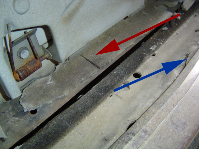
Here are the remnants of the two center filler pieces adjacent to the fuel-filler door that doubles as the license plate holder. The blue arrow shows all that's left of the original part I ordered. The red arrow shows the part I originally thought to be salvagable, but which in fact necessitated an additional parts order... from "E & K Bumper Fillers," this time.
This time my parts arrived in a couple of weeks, which "E & K Bumper Fillers" informed me of up front. Now that's more like it! They've also got the best prices (as of 2010) and there's a link to their site on my links page. Unfortunately, the weather turned too cold to paint in the meantime, so the project languished for several months.
But I'm getting ahead of myself once again. Before the weather turned too cold (near the end of October), I was able to get all the previously purchased parts painted. The plastic pieces are supposed to be more durable, but the preparation process is a multi-step one that really eats up the clock.
The first order of business was to inspect the parts, (there will be the inevitable imperfections that need to be addressed), no matter what quality parts you receive. In my case, these amounted to little more than a couple of scratches and a couple of "pimples" in the surface of the plastic. Once prepped, one must clean the parts thoroughly.
By this point in time I've fully absorbed the principle that preparation is the key to a good paint job. Once I had addressed the couple of imperfections I found, it was time to clean the parts...yes the new parts. The cleaner removes several of the prime suspects that prevent paint adhesion: water and solvent-based mold release agents, wax, grease, even your own fingerprints as well as "other contaminants" whatever they may be.
Just cleaning the parts does not guarantee paintability. However, the cleaner I used contained "micro abrasives". Really sounds high tech doesn't it? Actually, these abrasives impart an almost imperceptible "tooth" to the surface. This is analogous to wet sanding before priming or between coats of paint.
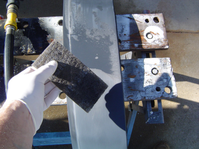
Dr. Brian to the paint booth STAT! I "gloved-up" like a surgeon as one more safeguard against my own oily fingerprints as I prepped the parts. I used a product called Scuff Stuff. My father-in-law uses this stuff (along with a gray ultra-fine scuff pad), to prepare plastic panels and bumpers, because it removes waxes, silicones, plasticizers and mold release agents. The nice thing about Scuff Stuff is that it rinses off easily with water. By the way, never use a green scotchbrite just because it's "handy." Your local body/paint shop supplier will have everything you need including filters, stirers, reducers and activators.
This ate up the better part of an afternoon as each part was scrubbed thoroughly before being set in the sun to dry. By the time I got this part of the job finished it was obvious I was loosing daylight as well as the ideal temperature at which to paint. There was nothing else to do but shut down for the day and take the parts inside.
Now you have some idea why you periodically see Caddies of this vintage running around with black bumper-filler pieces. They either don't have the knowledge (or the paycheck), to finish the job properly. The parts alone aren't cheap, I figure I'll be into this for about $450 or so (check figues!) by the time I'm done. But the job will be done right and look presentable.
Day 2 (10/18/09)
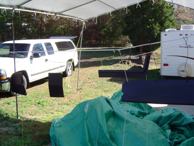
The second day we reconvened around 10am. The day was so nice (even wind-free), we set up shop outside, beneath a portable carport. We then tied three lengths of rope horizontally from which we hung the parts on pieces of shop wire.
We quickly discovered we'd have to anchor the parts better (to keep them in place while spraying), hence more rope from a lower hole of each part down to a length of pipe to serve as an anchor point. Once again, preparation (hanging the parts), took up the lion's share of the time. With everything in readiness, I gave the parts one last wipe-down with a mix of alcohol/water.
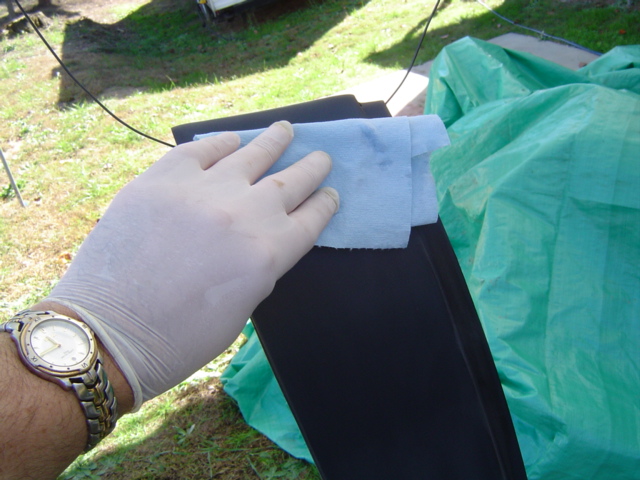
Here are the special "lintless" paper towels. While my father-in-law set up the spray gun, I focused on taking one wipe, turning the rag, another wipe, repeat. Check out my watch, that's real time baby, almost 2 hours getting to the final wipe down.
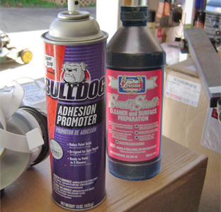
Once I wiped everything down, I left the parts to dry while I went to grab the can of "adhesion promoter"! There are other brands, but Bulldog (love the logo), came recommended, so that's what we used. Expensive stuff too...to the tune of $22.00 bucks a can! Ouch!
A few pictures up, you can see a shot of what the stuff looks like. You actually do get a pretty decent sized can...depending of course, on the size of the task at hand.
Between laying down two light coats of adhesion promoter (as well as fixing a finicky spray gun), mixing the paint and the activator...we didn't start spraying until 3 o'clock! Thankfully the actual painting process goes quickly once you get on a roll. I played cameraman while my father-in-law laid down the urethane paint. I haven't shot a car since the 1980's...I doubt the enamels and lacquers I used back then are even made anymore! I'm still on the fence regarding shooting Blue Thunder myself when the time comes, (but am seriously leaning that way), but I watched the process closely nonetheless.
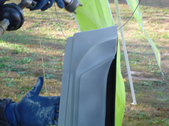

The above-left shot shows the first coat, which looks a little flat. Above-right: a second coat really brings out the gloss. The secret to getting a good finish (free of runs, drips or sags), is a combination of many factors. First and foremost, you need good conditions, about 70-75 degrees and low/no humidity is best. If you have access to a paint booth (or can whip one up on the cheap), more power to you. The paint to air ratio plays a key role and we wasted a little on a piece of scrap to get the spray pattern just the way we wanted it.
Then you have to hold the gun perpendicular to the surface, at the proper distance, watching the buildup of the paint carefully. My uncle called this "wetting it out" back when I painted my '73 Satellite with Centari acrylic enamel.
Oh, a word to the wise. Whatever you do, DO NOT park your vehicle nearby like my pickup is in this shot. The first time I got caught in the rain after this, the wipers sounded like I was sanding a piece of wood.
I had to Bon-Ami my windshield to get rid of the overspray. Although that helped, it's still not right. I'll have to polish it properly this summer...nothing like making more work for yourself is there?

"I AM YOUR FATHER LUKE." Yes well, Luke never bothered to paint his Landspeeder from what I recall. Back when I was young (indestructable, immortal & bulletproof), I simply slapped on a dust mask and called it a day. When I painted my GTO red, I was blowing red from my nose for days. Now that I'm older (wiser, mortal, & destructable under the right conditions), I realize how toxic this stuff is. Pros wear the equivalent of a space suit when they're "in the booth" spraying a project.
Probably overkill for the task at hand, but may as well keep good habits regardless. At least we had excellent ventilation! So there you have it should you face a similar project yourself. Of course the next step is to remove the old parts and install the new ones. I'll save that for another day.
Of course, I still need to get my Dad's car out of my carport so wifey can park there during the periodical monsoons we get. This was supposed to be a winter project... yet his Caddy is hulking in my carport like some sort of mechanical refugee of the Great Depression, attempting to establish squatters rights.
Day 3 (4/3/10) Change Out
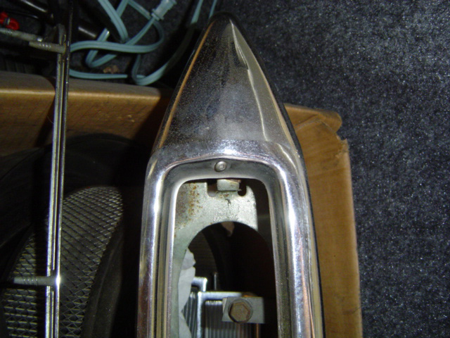
Saturday morning dawned bright and sunny, so I (having no other pressing obligations), decided it was finally time to say "out with the old, in with the new." Step one was to remove the chrome trim ring which surrounds the signal light pod, headlights and cornering/side marker light combo. Strictly speaking, it isn't necessary to remove the cornering/side marker light pod, but one of the tabs it mounts with was hanging on by a thread.
By the time I finally got my act together, it was crowding 90 degrees (in April!) so I retreated down to my basement workshop where I've got more hospitable working conditions. Of course this was only one of many trips I made that day.
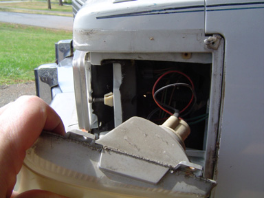
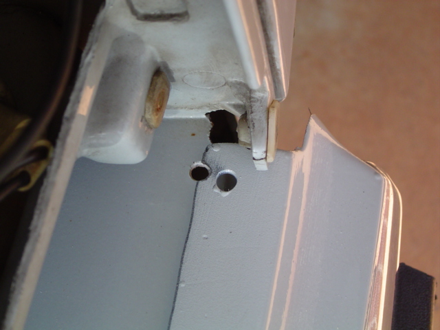
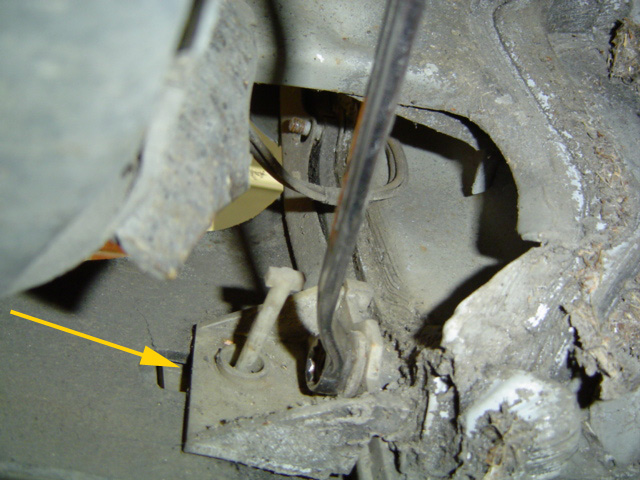
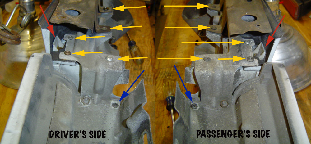
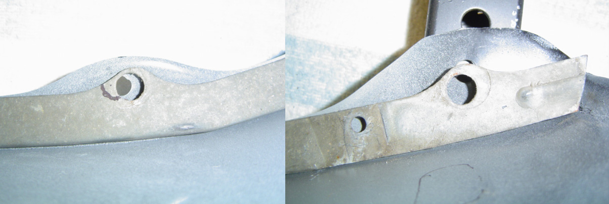
Back outside for more disassembly I plunged right in, this time going for the jugular by removing the actual panel needing replacement. The filler panel mounts from beneath with 5 bolts, securing the panel between the fiberglass header panel and a flat, steel bracket.
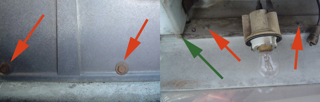
The red arrows show a couple of the bolt heads (from beneath) and threads (from above), while the green arrow shows a small verticle tab on the upper side. Not sure of its purpose, but the new parts don't have it. Also seen on the right: a signal light bulb, and fiber optic feed.
Hanging by a thread indeed! I'd no sooner set the pod on my bench than the tab let go (see inset). And people wonder why my projects take so long? Here's one reason! No stranger to such breakages, I pondered my options, the first being an epoxy based adhesive. Due to the stresses the unit is subjected to, I was hesitant to use my tried & true melt-it-together with a soldering iron technique.
The piece of wood between the marker light and cornering light was my attempt at devising a method of "clampage" as the epoxy sets up. Unfortunately, the tab protrudes at an angle from the "pod" making clamping impossible. My solution?
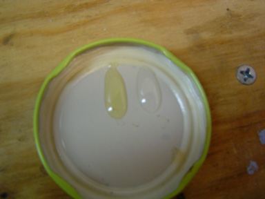
First, I whipped up a batch of 2-part epoxy using an old jar lid for a mixing tray. Like most DIY'ers, I keep a supply of empty jars laying around as containers for sharps, fluids or other small parts.
I'm trying to wean myself off such an antiquated storage system (several multi-drawer organizers attest to that) but having them around is just so darned useful.
Screws, nuts, bolts, washers even a small assortment of orphaned sockets have all found a home in recycled food jars. Naturally, the lids themselves frequently get pressed into service as illustrated here. Side note: plastic coffee can lids make good Bondo mixing trays too.

I tried every clamping method I could think of, no matter how wild the idea. However, I had to be extra careful, so as not to damage the already brittle plastic pieces. Came close to blowing my cool a couple of times here.
Epoxy may be strong, but it happens to have a rather thin consistancy. This (in conjunction with the amount of time it takes to set up), makes it difficult to get the parts aligned properly, particularly without clamping.
Part of the problem stemmed from the angle at which the tab had originally been afixed to the pod. It came out at approximately a 45 degree angle just to make things interesting.
Finally (after the 6th or 7th time I had to retrieve the tab, clean it, re-epoxy it and re-position it), I succumed to exasperation and fired up the old soldering iron. With the epoxy sandwiched between the two pieces and holding it at the proper angle, I melted the short edges together.
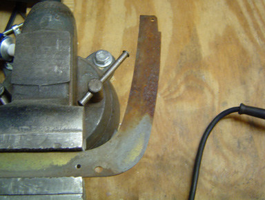
Having won the war with the recalcitrant cornering lamp pod, I moved on to attack the retaining bracket. The last thing I wanted was for this mess to leave streaks of rust all over my new body parts. I threw a 6 inch 80 grit sanding disk into my 'lectric drill and went to work.
Once I got down to shiny metal, I primed it and then shot it with some semi-gloss black. I used Krylon products this time out since I was after protection over appearance, since the bracket won't be seen once the chrome trim ring is reinstalled.
My camera batteries were charging during this part, so no action shots I'm afraid. I'd already fallen far enough behind schedule as it was.
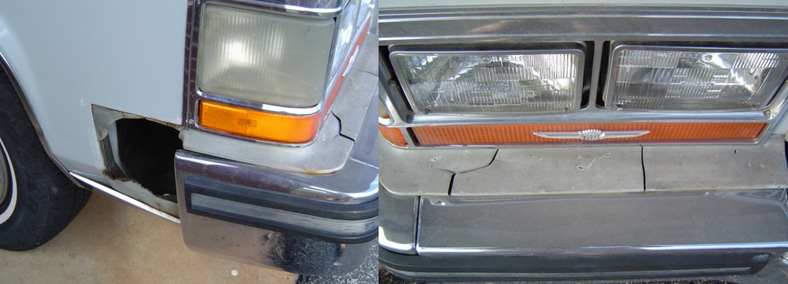
The mounting tab issue solved, there was the small matter of appearance to be addressed. Driven by ever tightening fuel economy guidelines, the auto industry has (over the years), implemented several changes to address weight savings. Traditional sealed beam headlights/signal lights are heavy, so plastics began being phased in. As with most solutions however, although plastic did reduce weight, (even providing easier bulb replacement in most cases), the tradeoff was the fact that plastic is simply not as durable as glass.
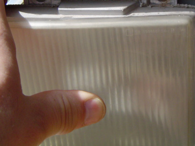
BEFORE
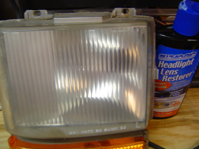
AFTER
As plastic ages, it yellows or gets "foggy" over time. This (thankfully), is a mild example. I've seen some so yellow as to be opaque. As tends to happen, a whole cottage industry has sprung up to address this issue. All you need to do is hop in your car, go to the local parts store and score a bottle of "headlight lens restorer." Touted not only as a yellowing remover, but even preventing "re-yellowing" this is basically glorified polishing compound and the stuff's not cheap. Since my lens had a couple of deep surface scratches, I used some 1000 grit wet sandpaper for my initial pass or two (using a circular motion), followed by some 2000 grit before working my way up to the lens cleaning compound. I was impressed with the results... there's probably some other cleansers in the mix as well.

Finally, after several false starts, it was time to actually bolt up my new parts. At least that was the game plan. Whenever you use after-market parts, there are bound to be some fitment issues. I was impressed with the quality of the parts, but now I needed to start "modifying."
Other differences not immediately apparent were the small vertical tab (just in front of the curved cut out), as well as a closed verticle edge (red arrow). No problem for Mr. Dremel! If you don't have one of these marvelous little gems, you really need to add one to your tool arsenal.
Whether I'm working with plastic, metal or wood I've found it to be indispensable for many of the projects I've tackled through the years.
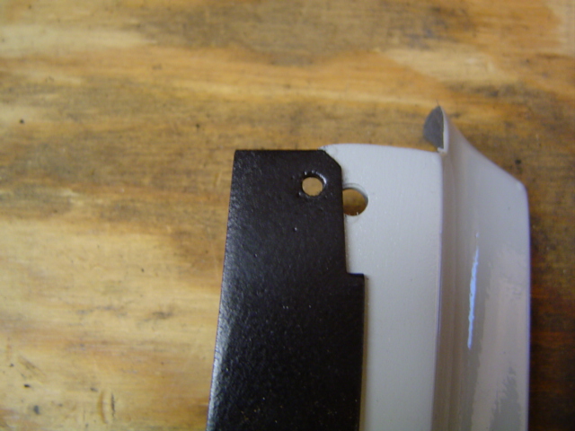
After marking the area to be removed with a Sharpie, I set to work cutting out the notch I needed. It looks like I'm way off the mark, doesn't it? Well, after years of doing this sort of stuff I've learned to "sneak up on" cuts like this. It's duck soup to remove the material, but if I make a mistake, I'll be boned. Needless to say there were a lot of trial fitments as I took off a little material then went out to check the fit. Then back down to the shop to grind off a bit more plastic. Takes a lot of time that way, but then I tend to be quite meticulous with my projects.
There we go! Not too shabby even if I do say so myself. Granted, it took a bit of doing, but I'm pleased with the result. As seen in this shot, most of the mounting holes lined up just fine.
There was a small raised "nib" on the rubber piece (to help locate it on the metal bracket), but the lack of it shouldn't affect the appearance at all.
Now all I need to do is double-check the alignment of all the other holes and I'll be in business. Remember when I said most of the holes lined up? Most does not mean all. This was precisely when the next hurdle reared it's ugly head.
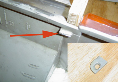
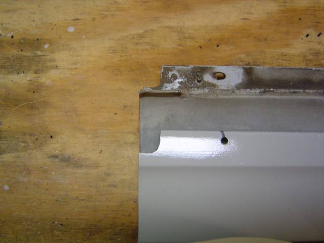
Here we go again. It took me awhile to come up with a solution for this. As seen in this shot, the mounting hole clears the metal bracket perfectly. I experimented with a large-headed screw (from the top side), but the threads were far too big to fit. I couldn't help thinking if GM had just left the notch out of their bracket design, I'd be home free.
No such luck...besides, for a project like this I didn't want to weld more steel on or fabricate a new bracket. I contemplated drilling a new hole in the fiberglass header panel (attached to the car) which holds the headlights etc., but that would miss the bracket as completely as the hole in the filler panel itself. So the steel bracket and the header panel had to stay as they were.
In the end, my solution was as inelegant as it was simple. With no other choice, I simply cut a notch (seen here) in the filler panel and lined up all the other holes as necessary. The steel bracket works by clamping the filler panel between itself and the header panel, so I just went with what I had. It's not a perfect solution, but it will have to do.
In the final analysis, the plastic filler panel is at fault, being off just enough in this one dimension to not fit properly. As long as all the other dimensions match up, I won't be too concerned, since the chrome bezel should cover up all the unfinished parts anyway. Darn my perfectionist tendancies.
In retrospect, I could have removed some of the width of the filler panel (from the left edge), re-cut my curved notch and re-drilled the other 4 holes. If I had to...I guess.
Most folks I know would line up as many holes as possible and fix the odd man out like I did. Who knows...maybe when I go to line up the chrome bezel I'll be able to tell if I need to do that. At this point my approach is as good as any.
The shadows were getting long by this time and even though I still had more parts to re-install, I was tired and that meant it was time to quit for the day. The final result makes all the difference in the world, when compared to the opposite side of the car.

Ta dah! Final assembly speaks for itself. A few details worth noting if you plan on tackling this project for yourself. The blue arrow shows just what purpose the little vertical tab (that I'd been pondering earlier), served. Oh well, it's on, looks good and no further modifications were necessary.
The yellow arrows show two trim screws that serve multiple purposes. The left goes through a mounting hole on the signal light pod, while the right goes through the (newly re-attached) cornering light pod then through the signal light pod. Only the center screw holds the signal light in place before the trim ring goes on. Turtle Wax Chrome polish worked wonders here.
Day 4 (7/7/10) Rear Disassembly
How I spent my summer vacation. In grade school, nothing inspired pure dread like those six little words as uttered by a teacher wanting a "no-brainer" lesson plan. It wasn't bad enough that summer vacation was over... lets drive that fact home with all the subtlety of a fire axe to the head why don't we? So, here's how I spent my week off (following the fourth of July holiday) this year. Perhaps some year I will actually use my time off for an actual bone fide vacation.

The first step is to remove the tail light pod. I removed the light bulb sockets from the back side and the chrome trim from the face. The tail light pod was just big enough to not clear the opening. Maybe that's why the driver's side one was broken. The above-left shot shows my solution, cutting a small clearance notch in the housing.
Above-right: confirming that the trim ring does indeed cover my little modification. The secret is grind a little, check the clearance, then grind a little more. Took me about six or seven tries to get it right. In the end, the tail light pod just clears the main fin assembly.

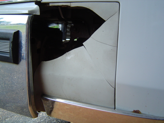
Here's why I was so reluctant to force things on the passenger side. Some knucklehead beat me to the drivers side and this is the result. This means I get to break out the epoxy one more time to effect repairs.
So, the tail light pod is on my bench awaiting repairs and the tail-fin assembly is right next to it scheduled for a little notch cutting of its own.
Needless to say, I'll be sweating bullets when the time comes to reinstall this part. This plastic tends to get mighty fragile over the years, probably due to the extremes in temperature to which it constantly gets exposed. No worries though, industrial epoxy is your friend
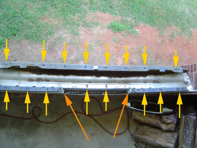
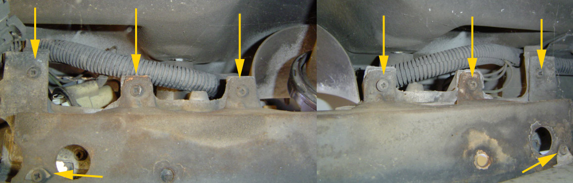
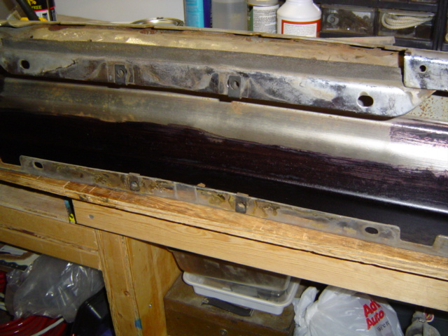
But first, a rousing opening shot of the first two brackets requiring removal. Obviously one secures the outer edge of the bumper filler, the other secures the inner edge adjacent to the trunk lid. Also readily apparent in this shot are the grid-like adhesive remnants of Dad's duck tape repair. Yeah, Dad attempted to fix the fin extensions with duct tape. On a Cadillac!
Removing those was easily accomplished using the greatest tool known to man... the thumbnail! Don't laugh, a little Turtle Wax white polishing compound applied with a damp cloth and you'd never know the difference. Of course, that left a clean spot compared to the surrounding area, but I'll deal with that later on.
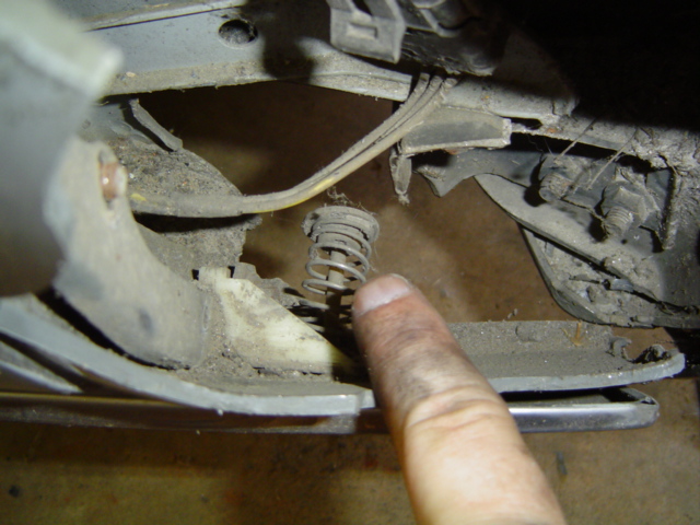
Before I could remove the remnants of the bumper filler, I had to unbolt the retaining bracket that attaches it to the car. The bottom bolt of which also passes through a white plastic bracket, to which is attached a clever little spring-tensioning device which holds the rocker panel trim tight to the bumper filler.
I released the spring by pushing inward and turning it 1/4 turn. If you've ever done a brake job on a drum brake system, the concept is identical.
Then I unbolted the plastic spring bracket to get it out of the way. This final bolt released the outside metal bracket which secures the bumper filler unit.
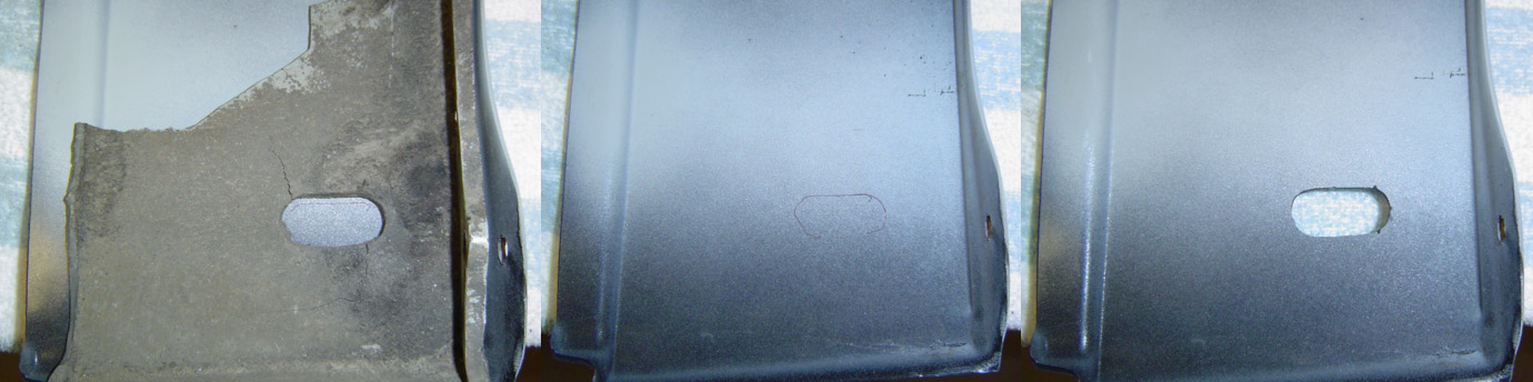
The yellow arrow illustrates yet another modification I'll have to make to my replacement bumper filler. The oval hole that provided movement for the original energy absorbing bumper is missing on my new piece.
Probably due to the fact that the parts I ordered were designed to fit several different years/models of full-size RWD Caddies.
I debated the necessity of doing this (I really hate cutting up special order parts) but other than leaving the trim loose, I did not see a viable option to the factory setup.
Another task for Mr. Dremel.
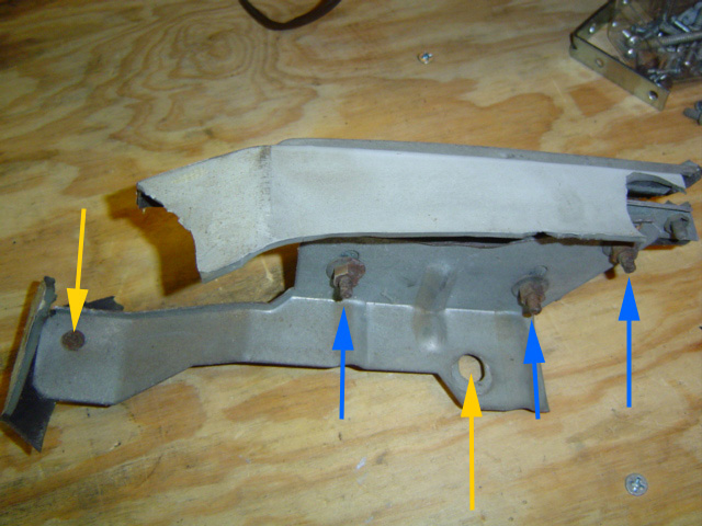
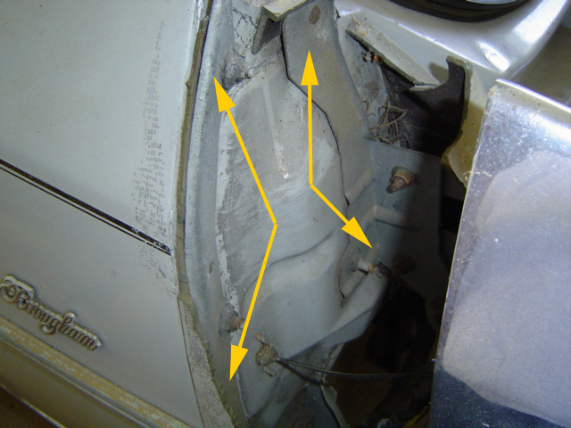
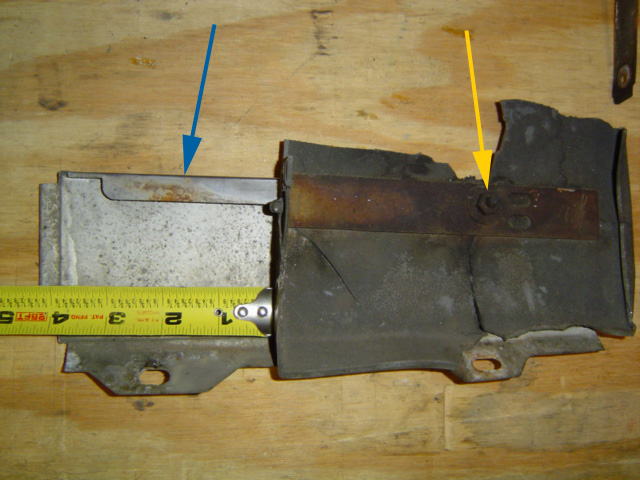
In addition to the outer bumper-filler bracket I also had to contend with an inner bracket along the edge of the trunk lid. Here's a shot of it on my bench, oriented as it mounted to the car, with the left side stud bolting to the top of the rear fender.
The yellow arrows illustrate the attachment points to the fender, while the blue arrows indicate where the bracket is bolted together.
This two-part bracket is easily dismantled by removing the three nuts shown. A rather easy way to separate the wheat from the chaff as the saying goes. However, I think I'll hedge my bets a bit and keep the unused part on the side... just in case you understand.
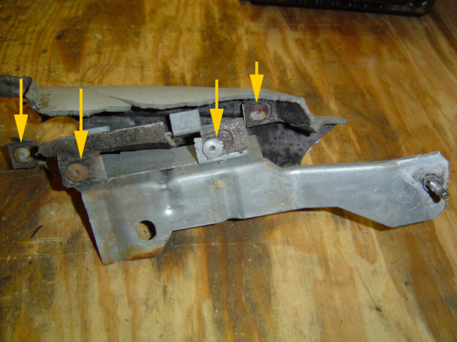
With the bracket tipped the other way, you can see the extent to which Cadillac went to ensure the bumper filler material stayed put. Wow! There's no less than four rivets holding the filler material to the metal bracket. Too bad the material decayed around them, as the rivets are still in place.
Since my new ABS plastic parts have no provisions for rivets (nor will any be needed in all likelihood) I'll separate the two halves and simply use what I need.

Here's one last look at the riveted section. If you look closely at the left side near the bottom, you can see a small speed nut attached to a small nipple of bumper filler material. More Cadillac overkill.
I gotta give them credit, they pulled out all the stops when mounting the bumper fillers... it's just too bad the material they used was flawed. That's one reason I decided to go with aftermarket parts.
Did the OEM material simply degrade over time, or was it exposure to UV sunlight that caused the deterioration? Not knowing for sure, steered me away from NOS (new old stock) simply because of the level of work involved.
So, here's what I'm left with. Will this be enough support for the new piece? I'll have to examine things closely once I get to the re-assembly stage of things. For right now, this looks to be all the support the new bumper filler will need. Famous last words.
This is the only drawback to using non-stock parts. Sometimes you have to perform some modifications or fabricate some additional supports for everything to come together.
This may be one more reason why so many Caddies of this vintage are running around with big chunks of their bodies missing. Cost not withstanding, you need to find a competent body shop to do the work.
Next I removed the bottom mounting bolt of the fin assembly with a 9/16 socket. I cheated just a wee bit here, (reaching in through the opening where the bumper filler used to be) but on the passenger side I sucked it up and removed the bolt properly (from underneath) using a 10 inch socket extension and a universal joint.
Good practice for the installation process coming up next. I gave each nut or bold a quick spritz of PB Blaster and had no problems removing the 20+ year old hardware.
The real fun began when I inadvertently knocked a clump of dirt loose... which the fan I had running immediately blew right into my face. And they say comedy is a lost art.
With the bottom bolt removed, it was time to remove the last two bolts holding the fin assembly to the back bumper. I'd read on the internet that you didn't need to unbolt the back bumper to replace the fin bumper spacers. This is true. It may be a tight fit, but the job can be done without removing the bumper. Keep in mind now, the back bumper is a 3-piece unit, this will be important shortly.
Each bolt got a generous squirt of PB Blaster from underneath prior to bolt removal. Did it help? Let's just say a couple of the bolts screamed bloody murder, but nothing snapped in half. So I'd have to say yeah, the stuff definitely helps. Besides, the aromatic fragrance of penetrating oil only serves to enhance the full "shade-tree" experience.
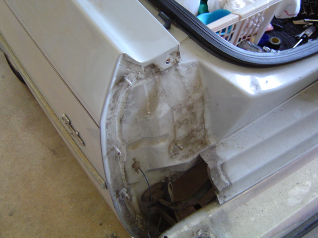
Whew! Finally all vestiges of the left-rear tail fin have been removed. Looks a little naked without it doesn't she? The duck tape track marks are suspiciously absent as well.
Upon further inspection (not to mention considerable internet research) I discovered (much to my horror) that I will, in fact, have to remove the center section of the bumper! Curses!
Rather than pull the whole unit, hydraulic pistons and all, I decided to unbolt the chrome cover of the center section instead. I was really hoping to avoid this, but it is the only way to replace the flat center section that butts up against the lower license plate filler piece.

Highlighted in yellow is an engineering blunder of biblical proportions. This piece of trim must be removed in order to facilitate replacement of the plastic center filler section as illustrated by the blue arrows.
Sounds simple enough doesn't it? The only problem is, there is absolutely no way to access the 6 speed nuts that hold this chrome trim ring in place other than removing the bumper!
This must've been an 11th hour solution to something and rushed into production. I guess the general consensus was, "hey if they can afford a Cadillac, they can afford to pay for fixing things." That may be true, but... are you freaking kidding me?
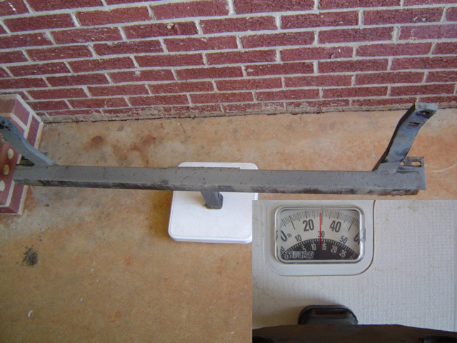
Before I can begin to remove the bumper however, I need to clear another hurdle. The previous owner obviously felt that such a large heavy car would be the perfect tow vehicle. For what, who knows. With the "fuel-miser" 307 under the hood, this baby has trouble getting out of its own way. All I know is that the darned thing is in my way and my Dad has never made (probably never will make) use of it, so it's sayonara trailer hitch. I'm sure he'll thank me for removing 30 pounds of iron from the back of his car. Not that it'll help his gas mileage all that much, but the poor overworked little 307 under the hood will no doubt thank me.
Check this out. Some 16 bolts later (yellow arrows) there she sits. This wasn't extraordinarily heavy, just bulky and clumsy to handle. The orange arrows show the stupid trim ring that caused all this work. The black plastic seen in this shot is evidently some sort of anti-rubbing device installed by the factory. The adhesive that held them in place began letting go almost immediately upon separation of the chrome section from the bumper backing plate. I'll probably just use some gasket adhesive I've got laying around when I put all this back together.
This was an insane amount of work just to access these stupid nuts. A few minutes work with my 10mm (more of GM's half SAE half Metric insanity) deep socket and the trim ring popped off. Two sets of tools to work on one (American?) car... lovely.
I couldn't help thinking that if GM had made the lower license plate filler and the bumper filler one piece, I could have separated the two halves of the license plate fillers, slid it out of the bumper recess and then replaced it. The trim ring fiasco would've been eliminated completely. I wonder if any other Cadillac enthusiasts have ruminated over this.

Well now... that certainly seems worth all the hassle to me. At least with this piece removed I can get on with the chief purpose I'm going through all this, replacement of the plastic bumper filler section that rides on the upper surface of the bumper.
Since it was another blistering 90+ degree day with lots of glorious humidity, I retreated to my basement workshop to cool off. A few brew-skis and my shop fans helped me re-focus. Now it was time for the next step... fitting the new plastic to the old bumper.
If you're thinking that was easier said than done, give yourself a little pat on the back.
After cleaning everything up, I couldn't resist a test fit to see how well the new parts worked with the old ones. The answer is, they don't. At least not without some modifications to one or the other.
I placed the plastic filler against the (way too narrow) slot in the bumper which held the original filler piece. I even gave it a tentative whack with the palm of my hand but what you see is how far in it went.
What this means is that I've either got to make the slot in the bumper bigger, or reduce the thickness of the filler piece. Not wanting to reduce the strength of the plastic by trimming it to fit, I instead tried a little prying on the bumper.
If you can guess what happened next, you win the kewpie doll. Naturally whenever I need to pry something I reach for one thing above all others... yep the big Craftsman screwdriver.
About 4 prys in, there was a loud "snap" and I was the proud owner of a freshly destroyed screwdriver. I tossed it into my truck so the next time I go to Sears, I can get a new one. Then I went down to the shop and brought up some chisels and a real pry bar.
Several test-fits later, it quickly became obvious that I'd break the welds on the bumper if I continued prying on it. This meant I only had one option left, so I marked the filler piece and went down to my shop. I'll have to shave the thickness of the plastic down until it fits.
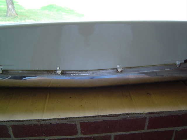
When I first examined the lower tag filler piece, I thought that it was held in place by 8 screws as seen below. I figured I'd remove the screws, replace the plastic filler piece and get some instant gratification Unfortunately for me, I figured wrong.
The screws in question do more than just tie the upper and lower halves of the license plate surround together. They also support (and are probably supported by) the two side filler pieces as well.
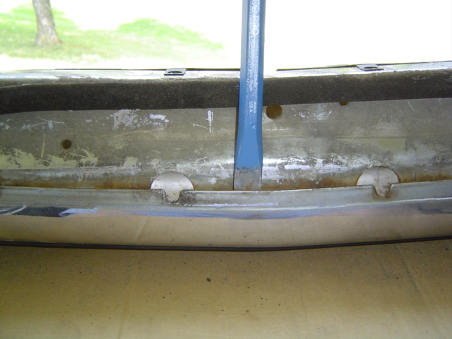
After removing 4 speed nuts from the license plate piece, I still couldn't budge it one inch in any direction. I kicked my shop pad under the back and rolled under.
Once I probed a little deeper, the solution quickly became obvious. I can't just remove the license plate surround because it is bolted to the same sheet-metal brace as the two wide pieces of plastic to either side of it. Drat.
This means I have to remove more nuts, but at least they're accessible from underneath. Needless to say, the bumper and the trailer hitch would've had to have come off anyway in order to reach these. Double drat.
Day 5 - Rust Treatment (7/9/10)
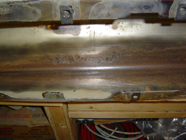
Upon close inspection, it quickly became clear I had some rust issues inside the chrome bumper cover. Being the anal retentive "mechanic" that I am, I naturally felt compelled to address this.
This type of thinking is what slows my projects down to a crawl at times. My original intent (replacement of plastic filler piece) quickly gets supplanted by repairing rust damage before it becomes a rust-through. But if I was running my own shop, I'd certainly mention it to the owner and offer some options.
In the past, I would have ground this down to bare metal and hit it with some Rust Oleum in an attempt to halt the cancer. This time I'm enlisting the help of a new product.

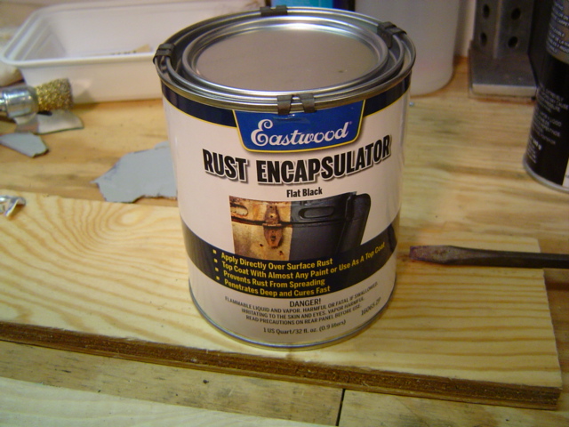
Many of Blue Thunder's restoration chemicals have been purchased from the Eastwood company.
Many of their products target the neutralization or sealing of rust. The theory seems to be that if you can seal the rust from air and moisture, you can halt the progress of the rust.
Being impressed with their products so far, I decided to give this a try. If I tried to grind out the rust there wouldn't be much metal left. Rather than delaying the project further, by trying to score a cancer free bumper, I'm giving this stuff a shot.
This is phase one of a two step process and the instructions are very explicit concerning the wait-time between coats of their products.

As with most products of this type, step one is to remove all the loose rust that you can. Here I'm applying the first coat of the beige liquid, which turns purple as it cures. The instructions state to give the surface a second coat after about 20 minutes when the color has changed. I moved on to other things (dismantling the left-front filler piece) while it dried, so it actually got about 45 minutes or so.
After the second coat, I am instructed to let the product cure for 48 hours. Then I can top coat it with paint or (according to the shameless self-promotion on the label) top coat it with Eastwood's Rust Encapsulator. This (naturally) would provide the maximum rust resistance possible.
I returned my attentions to the front of the car, determined to make some real progress. Wait just a darned minute here! Hold everything! What's that just above the rocker panel trim? That looks like a... A Rust Spot!
While I'm At It... 
Oh no! As it turns out, both front rocker panel trim pieces, by their very nature have rubbed against the paint, causing another rust spot. I can't just ignore it, it'll make the rest of the job look cheap. Not only that, but when it comes right down to it, this will never be as accessible to fix as it is right now. Here comes another snowball.
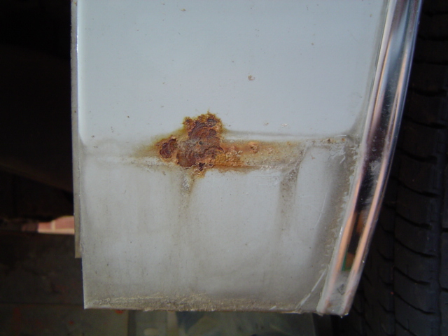
With the chrome strip removed, the rust damage can be seen in all it's glory. Since I'm already dirty, sweaty and investing this much time and effort, I may as well do the job right. Look at the size of this thing. At least I caught it before it got any larger or worse, completely rusted through.
Of course this means a trip over to my Father-In-Law's garage where the can of computer matched paint is sitting. I briefly considered a quick shot of generic light grey paint, but in for a penny as the saying goes.
Interestingly, the driver's side is the worse of the two. The way American roads are crowned (high in the center) I would've expected the exact opposite since water collects nearest to the curb.
The car came from Asheville NC (whose altitude fosters an abundance of snow during the winter months) hence the car has minor issues. Not as bad as Jersey, (where NJDOT turns snow into a corrosive paste the consistency of mushroom soup) smaller salt amounts still amplify the corrosive properties of the runoff.
I sanded the rust spot down to bare metal with some 60 grit sandpaper, wiped it with some alcohol (to remove any oily fingerprints) and gave it a couple shots of Krylon rusty metal primer. Detailed below is the sequence of repairs brought to bear on the dastardly rust spots.
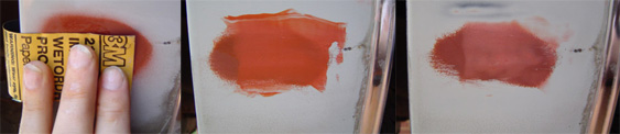
This is where patience is a virtue. Between sanding, puttying, re-sanding, re-primering, this part can take forever. But the end result is directly dependant upon the amount of preparation you put into the repair. When I'm finished you won't be able to tell that a repair has been made. For my money that's worth all the effort I'm putting into this.
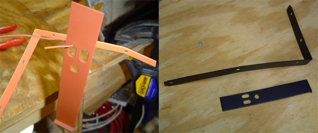
With the 48 hour clock running on the bumper, it was time to focus my attentions back on the front filler pieces. That meant separating the filler piece from the reinforcement brackets behind it.
Can you say "easier said than done?" Before I can de-rust the brackets and paint them I've got to separate parts that've been together for over 20 years. Let the games begin!
Of course I took full advantage of the missing filler piece and reached in through the empty space to free the sheet-metal bolts. At least on the driver's side. On the passenger side I worked from underneath with my trusty 1/4 inch extension and appropriate socket. It ain't easy, but yes, there's enough room to get the job done.

Here's a shot of the reinforcing brackets sitting on my bench in roughly the configuration they were mounted. This is also the side of the car which houses the battery. Guess what that means ladies and gentlemen? Right... corrosion and lots of it.
Since the original brackets had been cadmium plated, this thwarted the corrosion damage to a certain extent. However the L shaped bracket was rusted and pitted in several places. So I chucked my wire wheel into my electric drill and went to town. Once I got it down to bare metal I gave it a shot of rusty metal primer as well.
Next it was on to the rocker panel trim.
The blue arrow shows where the rust spot was on the fender panel. The yellow arrow shows the spring clip nut assembly.
I took a couple of measurements to help me determine where exactly to drill the necessary hole on the new filler piece. Then came the task of unbolting the chrome trim from the filler panel. This is where things got interesting.
I soaked the rusty nut with some PB blaster to hopefully forestall any breakage of parts. Then I attempted to separate all the parts without further damage. First, the formerly flexible filler panel disintegrated the moment I applied torque to the assembly. I set the pieces aside to use as a hole-drilling template.
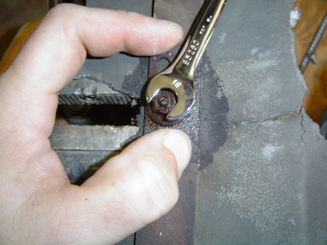
Next, the spring clip holding the nut popped out of the chrome rocker panel trim, so I tried clamping it in my bench vise. Nope. Unfortunately, the clip was so thin, I couldn't clamp it between the vise jaws. I ran the jaws in so they were just touching the clip, then I applied downward pressure to keep the clip from slipping up and out from between the jaws.
I began turning the nut slowly and evenly. Then I'd pause and give it another shot of juice. Then more careful tentative turning. In the end, it was all for naught. PB Blaster (having freed up numerous frozen mechanical parts for me previously) finally met its match.
Detailed below is the sequence of events that took place following the application of torque (via my 10mm wrench) to the rusty, PB Blaster soaked nut. And it had started turning so easily at first. So it was off to the auto parts store once again.
Busted parts!
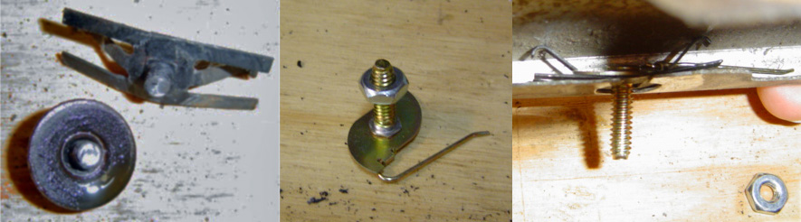
The national chain stores had little to offer. But here in the southeast, there are still small independent auto parts stores that somehow have what nobody else seems to stock. They didn't have what I needed, but they did have what I thought I could use. In the end I punched out the busted bolt head, inserted the new clip inside the old one and presto. Problem solved with new hybrid clip.
With everything else attended to, I returned my attentions to the front filler reinforcement brackets that I wire-wheeled previously. One final wipe down with alcohol followed by a nice even coat of Krylon rusty metal primer for protection. They dried for 24 hours.
After curing overnight, I gave each bracket a top coal of Krylon semi-flat black paint, similar to what the factory used for underhood items. Not a perfect match perhaps, but fine for my purpose of at least partially protecting the parts against future corrosion.
Day 6 - Rust Treatment Continued (7/11/10)
With the 48 hour clock having expired on the bumper, it was time to apply the next coat of protection. It goes against everything I've ever practiced, painting right over rust this way, but I'm trying out this product to see just how it performs in the real world.
This product comes in several colors (silver certainly would have blended in better) but with a quart on hand, I wanted a color that would have the widest possible use in other projects.
A smaller areosol can is also offered, but if it gets clogged, you're out of luck. Then you have a cloud of fumes to contend with. My basement shop isn't designed to handle the ventilation requirements so brush application got the nod.
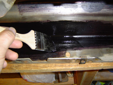
Black may have been a better choice as far as wider compatability among my various projects, but applying it over the purple Rust Converter really tested the old eyeballs. Even with two clamp on work lights hanging from the rafters, seeing where I'd done vs. where I hadn't done was a challenge.
Then of course there are the second coat instructions. I have roughly (due to varying temperature/humidity of the drying conditions) an hour to give it a second coat. Of course a thicker application will require a longer time to cure. If I happen to dawdle past 36 hours, then I have to scuff the surface with 320-400 grit sandpaper prior to application. I think I'll check it after an hour or so.
After an hour, the surface was still tacky, so I let it set up some more. By 10:30 that evening, it still had not cured enough (in my opinion) to warrant a second coat of rust encapsulator. By then, the work-week had kicked in and I didn't get back to the bumper cover for three days. So one coat of rust encapsulator it shall be. It's much better protected than if I'd done nothing, so time will tell just how well these products work.
Day 7 (7/17/10) Final Rear Disassembly

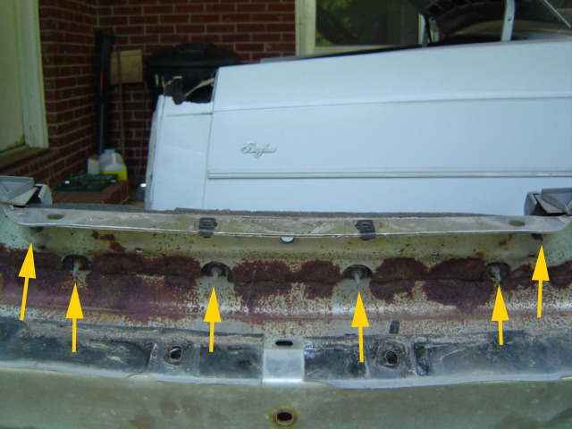
With my vacation over, I'm back to weekends only on the Caddy project. After exhausting all other avenues of disassembly, I finally sucked it up and removed the 6 speed-nuts holding on the remaining bumper filler pieces. The blue arrows show the four nuts in the license-plate surround, while the yellow arrows denote the six other speed nuts.
In the final analysis, it was actually better that I went this route. There were several other fasteners that were much easier to dismantle on my work bench than lying on my back out in the carport. The temperature reached a balmy 104 degrees in the shade with about 98% humidity.
Of course each wrench-slip sent a fine powder of road dirt sifting down into my face just for laughs.
Back down in my shop, I cracked open a cold one and jacked my shop fan up to high. There are two tabs on the license plate flange which hold the lower license plate filler in place. The holes on my new filler piece look for all the world like they were made by a 10 year old with a soldering iron.

I test fit the new piece to the old and marked where the holes needed to be enlarged with a sharpie. Once again I called upon the many talents of one Mr. Dremel, this time using a total of 3 different attachments. The final adjustments were made with my mini drum sanding attachment.
There are 10 screws total (yellow arrows) which hold the lower license plate filler in place. Two additional screws (blue arrows) hold the lower license plate filler to a common bracket shared with the two "wing" sections located to either side of the license plate surround.
The tabs on the license plate flange (red arrows) would have required far too much prying (the ever present specter of breakage hovering close by) for me to slip the filler back into place. A truly insane amount of disassembly perhaps, but it seemed the only logical course to pursue.

Finally, a milestone. One new reproduction part painted trimmed, modified and installed.
Booyah! Okay, maybe too much ado about nothing, but at least parts are going on instead of coming off. Ah, but the fun's just beginning.
I've put it off long enough. No more excuses, I have to get the center filler piece fitted to the recess in the center bumper section.
I've marked the piece, now I have to do some careful sanding to reduce the thickness of the edge that rides beneath the chrome trim ring.
Day 8 (7/24/10) Fitment of Parts
I got an early start Saturday morning and decided to trim/sand the center filler piece so I could re-hang the back bumper. This would turn out to be wildly optimistic on my part, but I plunged right in with both feet, determined to make good progress.
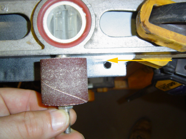
The yellow arrow shows the underneath side of the molded in mark representing how far the filler should fit into the bumper recess. I placed the piece on my bench and clamped a straight edge (the level) to it for my drum sander to ride against.
I measured very carefully, determined to do the job once and do it right. That was the plan anyway.
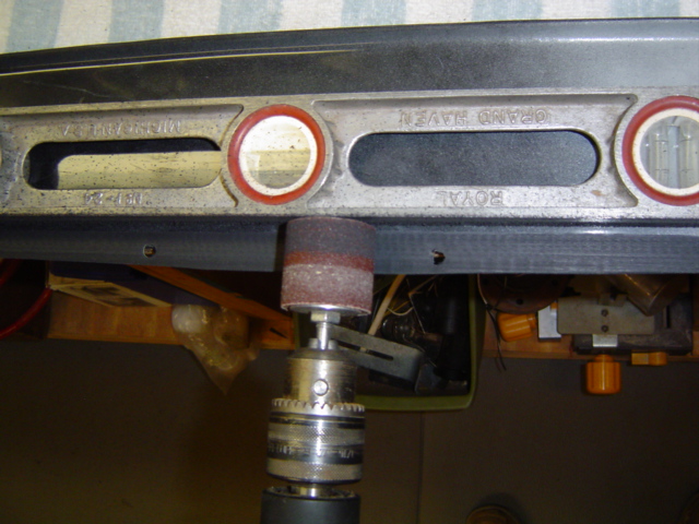
My plan worked beautifully, the drum sanding attachment (refills no longer stocked by Lowe's by the way) riding along my level like the two were designed to be used in tandem.
The only downside was, that I had to un-clamp and test fit frequently so I could be certain when I'd removed enough material.
I was using a worn 80 grit drum, so I wouldn't remove too much material too quickly. I failed to realize at the outset of this farce, that I was dealing with some TOUGH plastic. At one point I switched to a 60 grit mini-drum in my Dremel in an attempt to make faster progress. Then I switched back to the large drum attachment to level off my cut.
In my un-informed zeal, I neglected to realize that the thickness of the piece wasn't my only limiting factor. In fact the welds holding the recessed area to the main bumper section varied the depth to which the filler piece could be inserted.
Almost before I realized what was happening, the damage had been done. In this shot you can see how I've removed material between each of the mounting holes which solved the problem. Unfortunately, I was left with an even bigger problem to solve.
Two nasty splits in my new filler panel and an additional part to paint before re-assembly. Grrrrrrrrrr!
I regrouped around a bologna sandwich and a couple of beers then went back down to the shop to survey the damage. I didn't "burn through" the plastic with the sander but I'd weakened it enough that the pressure of the drill against the plastic cracked it. Great... now what?
I kicked around several ideas ranging from using a bead of silicone to using a layer or two of epoxy.
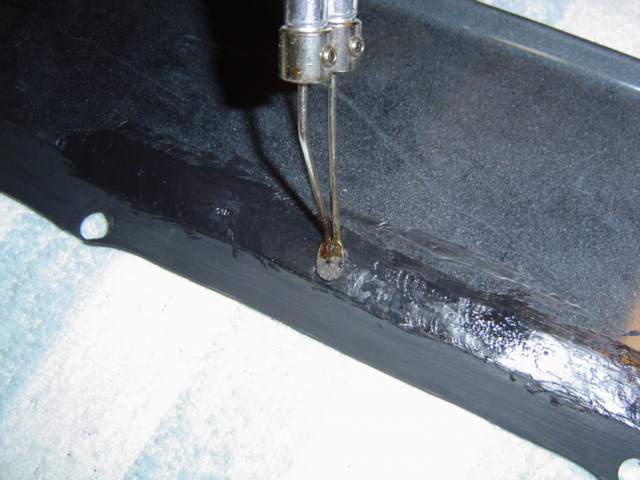
In the end, I grabbed by soldering gun, installed my smoothing tip and initiated repairs. Not the most elegant solution perhaps, but given the circumstances, I'm back in action again. I'll have to sand and repaint the piece, but my crass mistake will be hidden.
Encouraged by my resourcefulness in repairing the center filler panel, I decided to tackle the left rear fin. Since my virgin replacement panel has no provision for the stock spring bracket, I needed to create the proper opening.
Using the stock part as a template, I traced the opening with a fine point sharpie and went to work. About 5 minutes worth of careful Dremel-ing and the fin panel is ready to mount to the car... once the bumper is remounted that is.
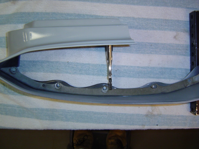
I temporarily clamped the outside bracket to the plastic fin replacement panel to check the fit. All things considered, the fit wasn't as bad as I thought it'd be.
Thankfully plastic parts have a certain amount of give, as long as you're carefull and don't force things.
Once I begin the arduous task of actually mounting this to the car is where the rubber meets the road, pun intended. All the mock ups in the world don't mean diddley until I actually mate the new parts to the old. The tricky part will be marking the stud holes in the piece so I can re-drill them. I'm sure a solution will present itself when the time comes.
Here's a close-up shot of the two odd men out. As near as I can tell at this point, these are the only ones that don't match up to the OEM outer bracket. If this works like all the other parts, I'll be modifying the plastic parts to match the car.
Since this was just a test fit on my bench, I'm not too concerned at this point. At least the parts I'm dealing with are plastic and easily tweaked, not to mention damaged. If these parts were pot metal, aluminum or steel, I'd be in a real fix.
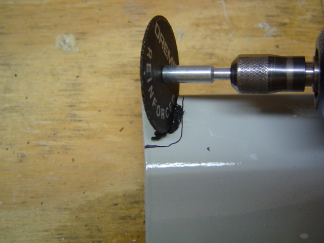
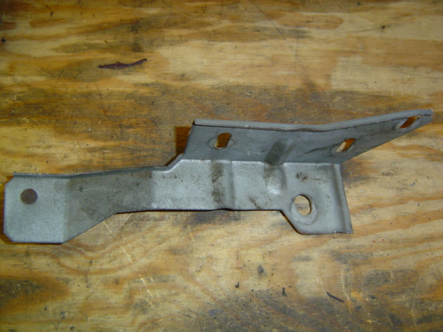
I did a test fit of the trunk-side bracket and discovered there is in fact room for the OEM bracket that had been riveted to the flexible filler panel. I zipped the rivets off using a cut off disk and bolted both OEM brackets back together again.
Although no where near as flimsy as the flexible filler panel, I still felt I should replace as much reinforcement as possible. Hopefully this will give the new ABS plastic parts enough support to prevent stress cracks. Time will tell I suppose.
This shot was taken from the perspective of where the flange mounts to the fender.
Engine Work
Odds & Ends (8/7/10)
So here I am, finishing up other aspects of the Caddy while I wait for a break in the weather to finish touching up the paint in a couple of places. The Monte project is bogged down in a morass of back-ordered parts, so what the heck.
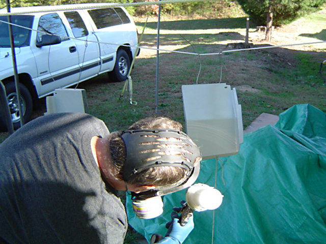
The last time I drove Dad's car, smoke was pouring out from underneath the passenger side wheel well. A brief investigation turned up a pair of leaking rocker arm covers that were letting oil seep onto the exhaust manifolds, causing the smoke screen.
I figured I'd fix this problem while I was at it, having done this to the Monte twice in the past. The biggest problem is simply getting enough under hood plumbing and brackets out of the way to facilitate removal of the covers.

First I had to remove all the support brackets (and there are a bunch of 'em) for the A/C compressor. I think I found the longest bolt in the entire automotive world this time out.
Not seen here are all the inevitable support items that had to be disconnected and folded out of the way to allow enough clearance for me to do the job at hand. The wires for the A/C compressor as well as several sending units had to be unplugged and folded out of the way.
Ditto all the spark plug wires (carefully labeled with duck tape and a sharpie) feeding this bank of cylinders. Next, I had to contend with the rat's nest of vacuum hoses that run all over the place, many of which were in various stages of decomposition.

Finally, after close to two hours of disassembly, I achieved my goal. The sludge build up isn't too bad considering the age of the car. Dad changes the oil every 5,000 miles or so, but there's no way to tell how previous owners maintained things.
Regardless, I cleaned the gasket surface of the head as well as the rocker arm cover so re-assembly would go smoothly. Copious amounts of brake cleaner (not to mention a huge pile of rags) comes in real handy at times like this.
I got super anal retentive and painstakingly removed the sludge from the rocker arm cover on the passenger side. Not so much on the driver's side though. The last person used silicone as a gasket (going right over chunks of old gasket material) so I peeled that off and cleaned everything thoroughly.

I've always had good luck with Fel-Pro gaskets as they are constructed of much higher quality than what the factory used. Not wanting to repeat this process any time soon, I felt it was cheap insurance to pay a little more up front for some quality gaskets.
Having gone through this process several times (with several different cars over the years) I have this down to a science. First of all, gasket cement is your friend. This will hold the gasket to the head (not to the cover... whatever you do) as you attempt to finesse the rocker arm cover back into position. The goal is to clear all the obstructions without knocking the gasket out of position.
I could clown this up by saying that chasing dropped rocker arm bolts is character building, but I won't. I will admit to unsuccessfully chasing one dropped bolt with a magnet (wasting an hour or so) before cleaning my hands, changing my clothes, hopping in my truck and going to the local Advance Auto Parts store to buy a new one. Made in Taiwan (naturally).
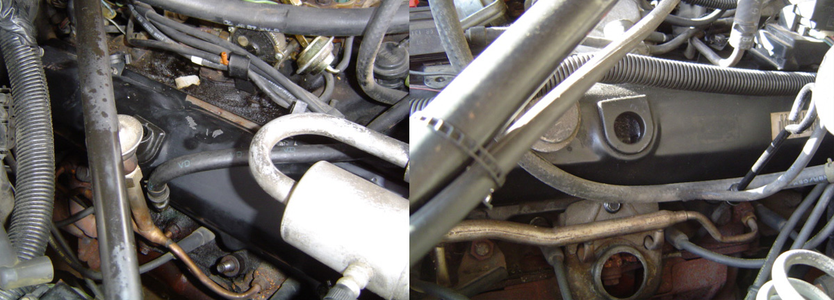
At any rate, the job is done, done properly and should greatly reduce the amount of smoke generated. This is another one of those jobs that folks put off, simply because of the labor charges incurred by having to disassemble half the engine compartment to replace a relatively cheap gasket.

Okay now here's one even I can't explain. All I can figure out is that the last person under here lost this bolt, or simply got tired and forgot it. Either way I rummaged through my organizers until I found the proper threaded bolt and fixed this too.
This is another benefit of being a dyed-in-the-wool petrol head. Over the years, I have amassed a vast assortment of nuts, bolts and fasteners of all kinds, never knowing when one particular part (and nothing else) will come to my rescue.
Originally sorted out in old cast-off aluminum baking pans (resulting in lots of digging with a screwdriver) I have graduated to those multi-drawer organizers found in almost any home center. Now when I need a missing nut or bolt, the search is much faster and less frustrating.
Sometimes, in working on older cars, you stumble across stuff that just makes you scratch your head. I freely admit to not having one hint of an idea as to why someone would deliberately pierce a wire with a metal pin like this. Was someone trying to take a voltage reading? Didn't they realize this could result in a short circuit... under the hood... you know, where fuel is present?
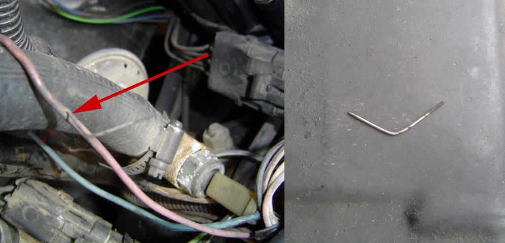
Not wanting to fiddle with removing and possibly damaging the dedicated connector, I went old-school and used black electrical tape for the repair. There are times when you just can't use heat shrink tubing.
The last time I drove Dad's car, I tried the cruise control. Nothing happened. Upon further investigation I now know why. Like most cars from the late 80's this one is plumbed with miles of vacuum hoses. Over the years the heat, various solvents and simply age have all conspired to degrade these hoses resulting in all sorts of problems.
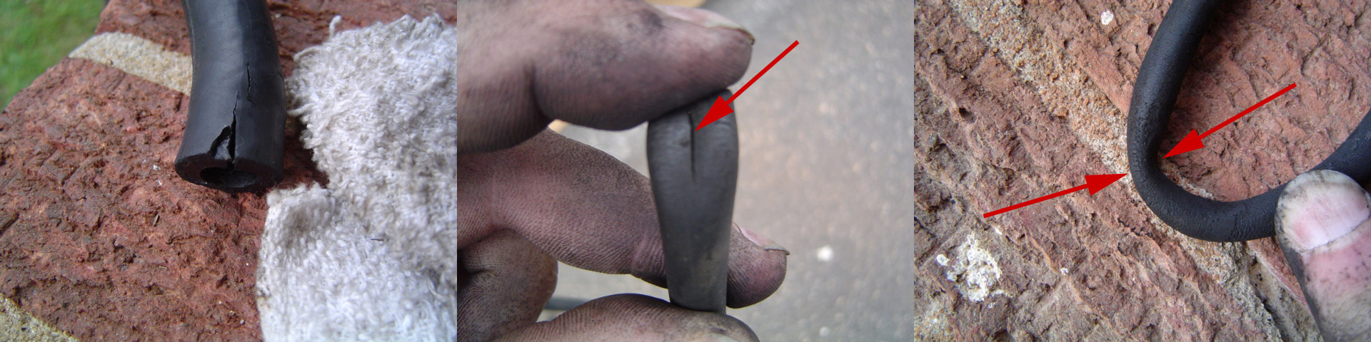
In fact, the hose in the upper right hand shot is the cruise control vacuum source hose. It had been pinched shut between the rigid fuel line and one of the many metal sensors found under the hood. Grease, oil, antifreeze and who knows what else had softened the hose as well.
As I was buttoning up the engine, I worked my way up to the air cleaner which was the first thing I removed. However, this milestone was bittersweet as it turned up yet another problem. The rocker arm cover has a crankcase vent, connected to the air cleaner by two rubber elbows and a metal pipe.
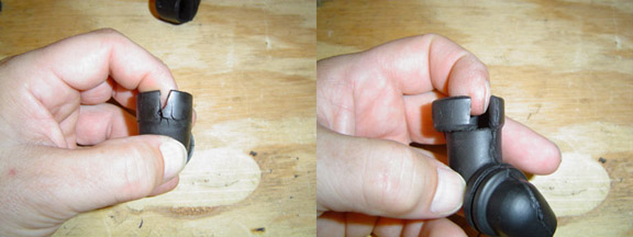
Both elbows had deteriorated to the point where they were doing little to contain the oil being vented from the crankcase. Fearing this would be a dealer-only item, I nonetheless piled into my truck and headed down to Advance Auto Parts. He didn't have what I needed... in stock. We perused the HELP catalog and found the two rubber elbows listed! The parts guy said he could have them the next day.
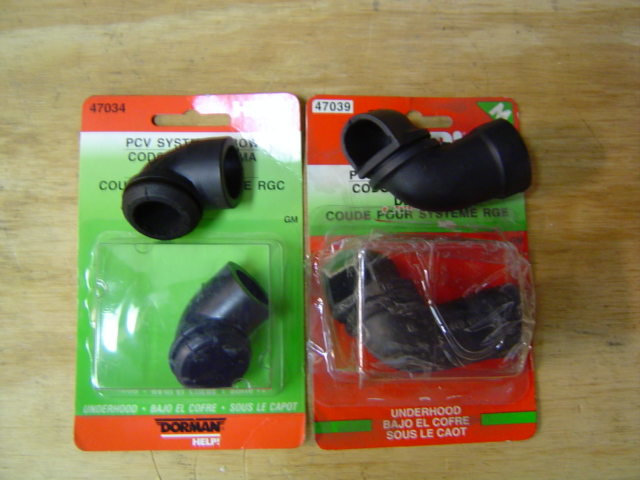
Sure enough, I showed up the following morning so we could compare the new parts with my battle scarred veterans. I will admit to being somewhat stunned that both parts were exactly what I needed. Of course they weren't made in this country, but the savings was worth it.
I paid four bucks for one and three bucks for the other. If I'd gone to the dealership, they probably would've been 20 bucks each. One thing I've learned over the years is that the dealership is the LAST PLACE to go for a part. The markup on parts is truly obscene.
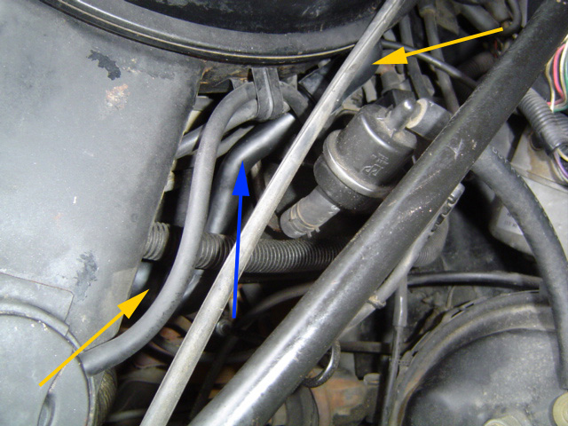
Here's a shot of both elbows (yellow arrows) as installed in their native habitat. I really did not expect to find exact replacements in the HELP rack at my local parts store, but it was a pleasant surprise. The blue arrow illustrates the metal tube connecting both elbows.
Of course they weren't made in this country, but there comes a time when you have to make choices. Dad, ever the frugal one, would have no problem with my decision as long as the problem gets fixed. In fact, most of what I've done in refurbishing his car has been sourced through the aftermarket, so this fits in well with the scope of my repairs.
Grillin' (8/14/10)
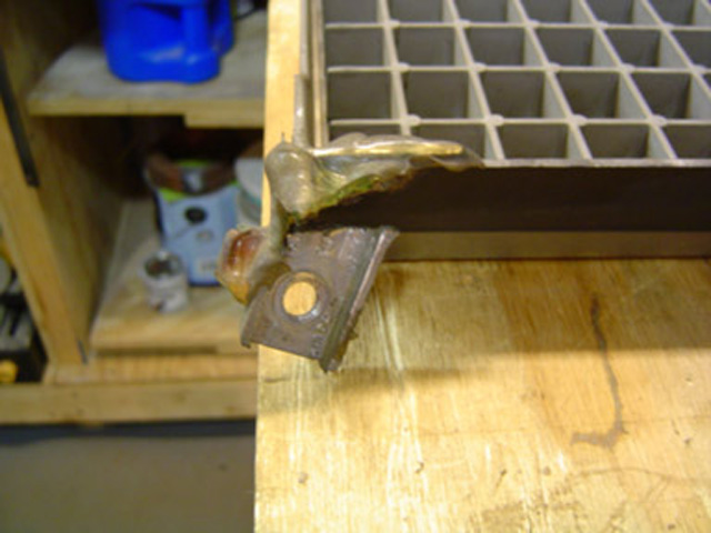
I braved the humidity once again in an attempt to straighten out the grill on Dad's car. The grille had been cocked ever since he purchased it and a new grille was beaucoup bucks. While I've got this think hulking in my carport, I decided to address this problem.
The grille is mounted with 5 bolts. The upper-middle bracket was missing and the two on the driver's side had broken and been repaired with some clear silicone. The silicone might've worked had it been applied with a trowel.
The upper-middle bracket would have required a Z shaped bend to have worked and that was a little beyond me. The side brackets however were a different kettle of fish.
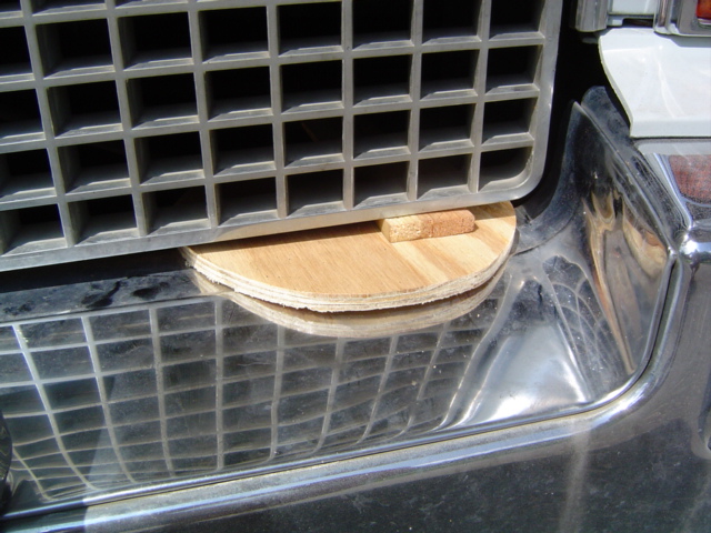
This was a multi-stage repair, due to the amount of measurements I had to make. I first removed the grill and ground down the remnants of the cast-in brackets. Then I went back outside, remounted the grill with the two remaining bolts and propped it up at the proper height.
I bent the metal bracket I was fabricating at about a 45 degree angle and using the original bolt holes mounted it to check the fit. I had to remove the bracket a couple of times, straighten it in my vise and re-check the angle again.
Once I was satisfied, I made a second bracket modeled on the first. Then I marked where I needed to drill my holes in the side of the grill and removed it once more.

I attached my brackets with screws, washers and nuts and re-installed it on the car. I placed the nuts on the inside of the grille (closest to the center) since there was a step that would help hide them. The screws on the other hand I ran in from where the bracket was going to be, using washers to spread the stress over a larger area.
I pre-mounted my brackets to the grille (since the screw heads would be inaccessible once it was fitted to the car) then mounted the grille onto the car. It was easy to fabricate the brackets out of some strap steel I had on hand. The tough part was all the trial and error fitting and bending and checking.
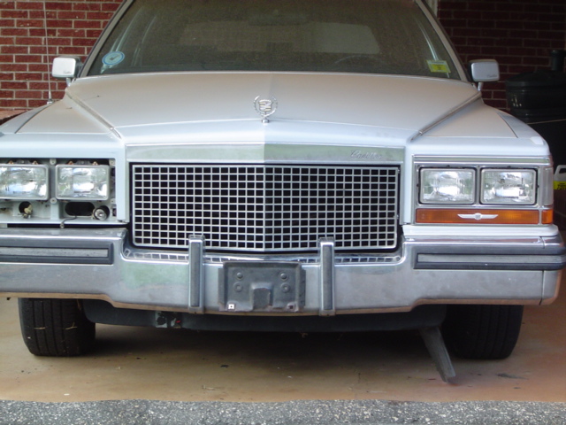
In the end analysis, the repair was a success. The grille now sits evenly in the grille opening instead of sitting on the bumper.
It was originally suspended above the bumper in order to allow it to telescope and rebound on impact. If you scrutinize it closely, the repaired side sits about 1/8" proud of the grille opening.
Then again, you have to be in exactly the right spot to see it and be looking for it as well. It more than matches the rest of the assembly much better than before and besides, this thing isn't exactly headed for the Pebble Beach concours run any time soon. Done!
Re-Assembly Continues (9/10/10)

While I was stuck waiting for a break in the weather, I also pulled off the front air dam (which had previously been fixed with duct tape and a couple of zip ties) and took it down to my workbench.
Once I removed the duct tape goo, I placed a piece of aluminum angle-iron behind the plastic and pop-riveted it into place. One of the bolt holes had been broken off, so I replaced the missing plastic with aluminum and drilled a new mounting hole.
I also discovered two missing attachment bolts that I replaced, before fogging the repaired area with some semi-gloss black paint. My repair is more subtle and stronger than the previous repair.
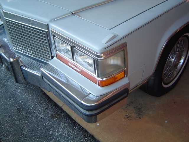
Here's a shot of the completed front bumper filler installation. I also took some extra time and used my "plastic headlight polish" to remove the oxidation from the plastic signal light and side marker lenses.
I also used my Turtle Wax Chrome Polish on the "chrome" headlight trim. It's only chrome-plated plastic trim, but it seemed to give everything a good cleaning and a little extra sparkle, so I did both sides. Once I wash and wax the car it'll really add to the overall effect of the car having been cleaned and detailed.
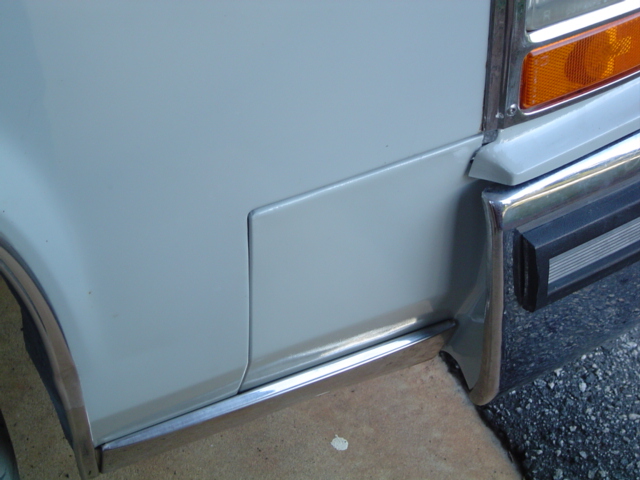
I mixed up a small batch of the paint I'd used previously and used a Preval kit to shoot the areas in question. Granted the spray pattern isn't as fine as a DeVilbiss gun, but since the areas are low and partially covered with chrome trim, I went for it.
It sure was a big relief to get this accomplished. The biggest problem was waiting for the weather to cooperate. Once it did, presto, I re-gained my forward momentum once again.
The area behind the square filler was not painted. This will give some idea of how closely the new paint matches the old. Only the small area behind the chrome trim was touched up.
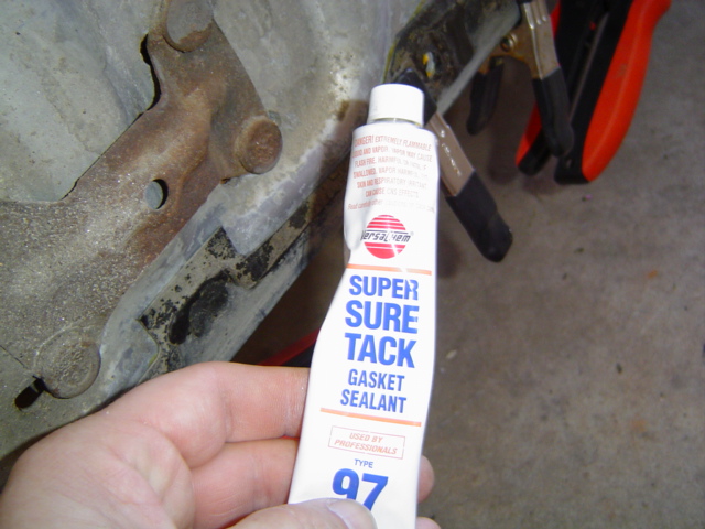
First I had to re-glue all the plastic "rubbing strips" that Cadillac saw fit to place between the backing plate of the bumper and the outer chrome shell I was working on. I cleaned the old factory adhesive off with brake cleaner, followed by some denatured alcohol as final prep.
I decided to use some high tack gasket adhesive. I had almost a full tube of the stuff and used a plastic bondo-spreader to evenly coat the parts.
I applied the adhesive, let it set about 10 minutes to get tacky and pressed it into position. My clamps were probably overkill, but I didn't want the plastic strips falling off.
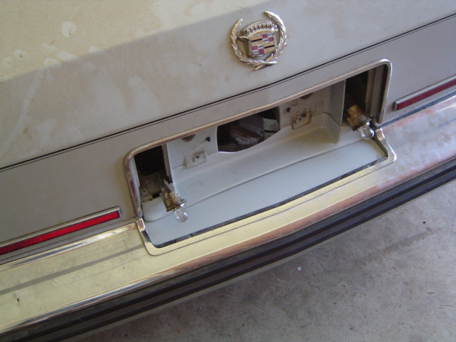
I used my trusty floor jack to position the bumper shell and a couple drops of PB Blaster on each bolt. Everything lined up perfectly and the re-assembly went off without a hitch. I still have to re-install the backup lamps, but couldn't resist an in-progress shot.
I was originally miffed by having to go through all this disassembly just to replace the plastic filler piece. But once I discovered all the hidden corrosion issues needing attention, it was worth the work to do the job right.
For it's age though (and the fact it was driven at least partially in the Asheville NC winters) it wasn't the worst I've ever dealt with.
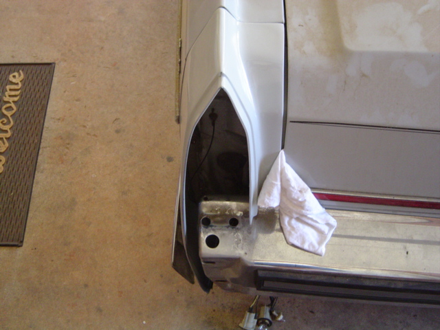
The shadows were getting long and I was tired, but I just couldn't resist mocking up one of the fin extensions. I had to elongate a couple of the holes to match up to the studs on the rear fender, but overall the fit was pretty good.
The problem I'm having is the fact that the original fender extensions were mounted to the brackets keeping the trunk lid gap consistent.
My plastic replacements however are not mounted to the brackets and I need to find a way to keep the trunk lid from contacting the new extension. The rag is my stop gap measure to protect the finish, until I figure out a proper and permanent solution.
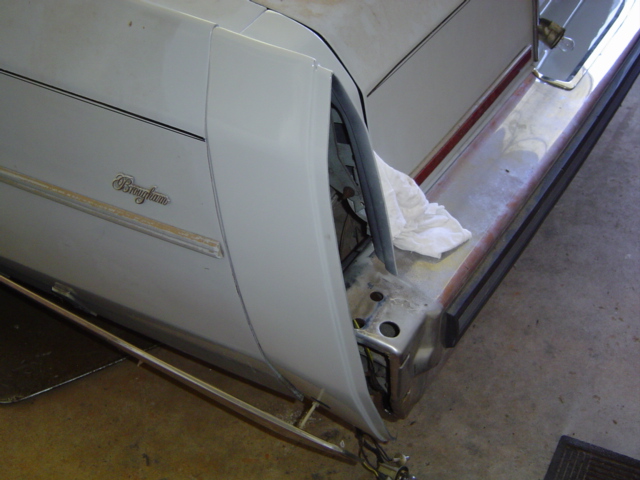
Although difficult to see here (the car will be washed and waxed before its return) the paint really matches quite well. The difficult part will be getting the fender extension to match up with the fender lines. I've had to adjust the mounting holes in the plastic accordingly.
Even though I measured and transferred the appropriate hole, the spring clamp "T-stalk" didn't quite match up. The bracket looked like it would slide rearward inside the chrome trim, and sure enough a couple of taps with a small tack hammer solved the problem.

Round 1 saw me re-installing the trunk-lid-edge bracket in the same position it'd been in prior to removal. That created interference between the fender extension and the trunk lid. It also resulted in an uneven fender gap.
Round 2 saw me moving the bracket away from the trunk lid to the maximum allowed by the slot in the bracket.
This got me closer to my goal, but the fender extension still sticks out too far. I may have to resort to a screw or rivet to physically attach the plastic to the bracket, mimicking the factory rivet method. I can pull the plastic extension into a position where it provides the needed clearance... I just have to hold it there.

I mocked up the chrome tail light housing to see if it would help align the fender extension and provide an even panel gap. It helped to a certain extent, but did not completely solve the problem.
After many trial and error test fitments, I finally realized there was no solution BUT to mimic the factory rivet approach. But the replacement parts have no provisions for this.
I briefly considered epoxying a bracket to the plastic extension, but with my luck it would last about a week and then come loose. I didn't want to drill an unsightly hole in the new fender extension, but I slowly realized I had no choice.
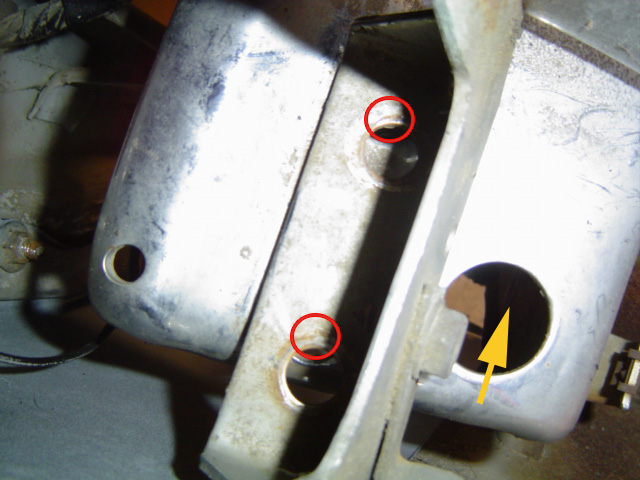
With the tail light housing held in position where it will actually hold the plastic fender extension in proper alignment, I'm left with this. The factory holes in the tail light housing are way off compared to the mounting holes in the bumper. If I hold it where all the holes line up, the trunk lid still hits the fender extension.
Even using a screw to pull the fender extension into position, I'll still have to elongate the holes in the tail light housing bracket. (The red circles indicate where I later elongated the holes, the yellow arrow the slotted third bolt location.)
But first, I have to devise a method of attaching the filler panel to the bracket without it looking all bollixed up.
I hopped into my truck and went to see what I could come up with. My initial idea was to use a small carriage bolt, thinking I could cut a square hole in the plastic and the head wouldn't look too out of place. Every one I found was way too big for the job at hand. My next idea was to use a stainless steel screw and nylock nut to hold the tension just so. Again, that solution looked tacky and ham-fisted.
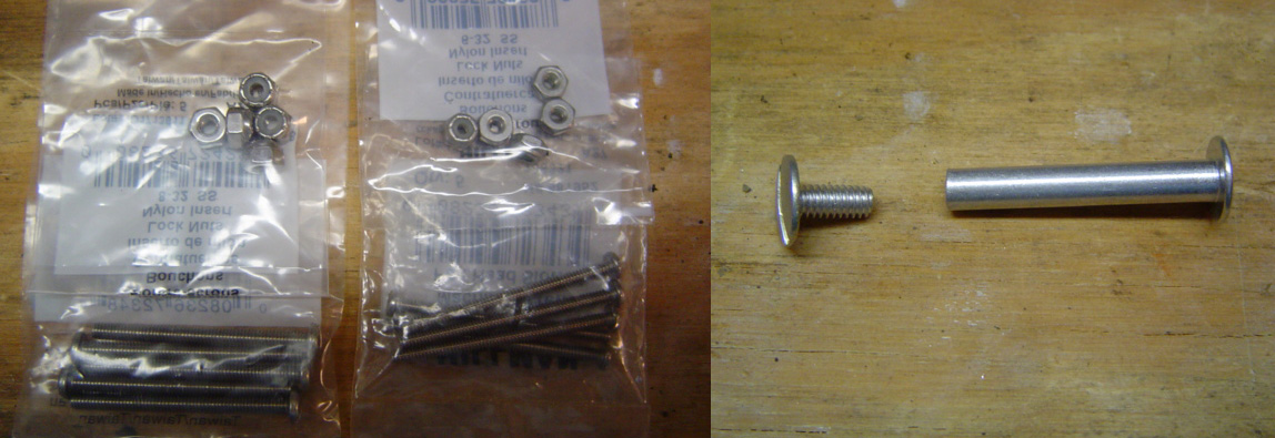
Then I stumbled upon the small aluminum fastener seen above right. It has a small, relatively flat and unobtrusive head on the side that will be seen, while the inside can be screwed tight with a lock washer in place. I can Dremel off enough length to provide the necessary pull on the fender extension. Simple, effective and at least partially professional in appearance.
I carefully measured the distance from the inside of the fender extension to the bracket and came up with 1 1/4 inches. I bought two fasteners in 1 1/4 and two 1 1/2 just to allow for "adjustments". The 1 1/4 turned out to be perfect, so I began cutting off what I didn't need to pull the fender extension in.
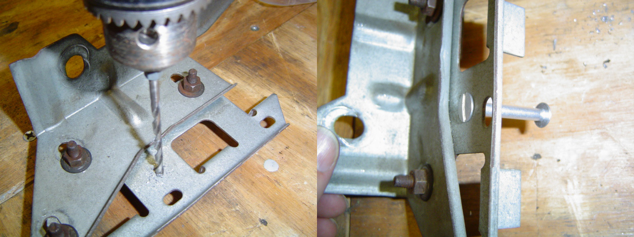
Above I'm drilling a hole that is just large enough for the threads of the screw. This will allow the head of the screw and the aluminum spacer to grab the bracket solidly. My goal is that anyone not well-versed in how Cadillac assembled their cars will never spot my little bit of re-engineering.
Re-Assembly Concludes! (10/26/10)

Ahhhh, finally. Once I drilled the necessary hole in the plastic fender extension and mounted the tail lamp assembly I took another snapshot.
Hard to see isn't it? That was the whole point of making a trip to Lowe's and rooting through their many drawers of oddball hardware. I have no idea what the primary use of this thing is (nor do I particularly care) but it worked the way I wanted it to and was fairly unobtrusive to boot.
The scratches of black adjacent to the new fender extension (just above the chrome bumper) are wear marks from the factory unit whose shape was just a wee bit different. I'll touch those up later if I have the time. After all, you can only see them when the trunk is open.
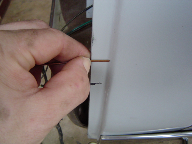
The new plastic fender extensions have a deeper lip than the original units. I grabbed a hunk of wire I had in my toolbox and measured the lip with my fingernail, later marking the copper with the edge of a file.
Granted this may not be the most accurate system ever developed, but as long as I'm close, I don't care, since the edge will never be seen when everything is assembled.
Even being as careful as possible during my initial test fitment I managed to scratch some paint off. Once again, the chrome tail fin housing will cover up this gaff.
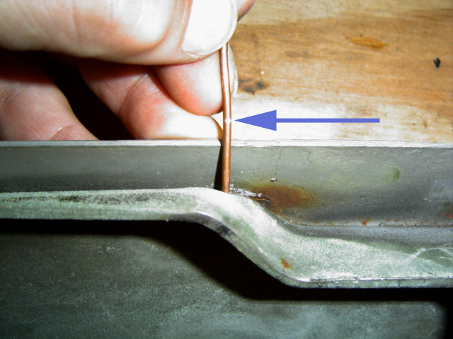
The blue arrow shows the file mark I made in the copper wire. The new plastic fender extensions are just about 1/4 inch deeper than the originals. This means that I'll need to modify the chrome tail fin by grinding away the interfering pieces.
There were two places where some factory welds had to be ground down and two other places where the steel flared out into the area needed by the fender extension piece. Every place else, I had more than enough clearance to mate the factory parts with my aftermarket ones.
Why didn't I modify the plastic instead?. Good question. My actual plan was to modify the chrome units first, then if necessary I'd modify the plastic for even more clearance.
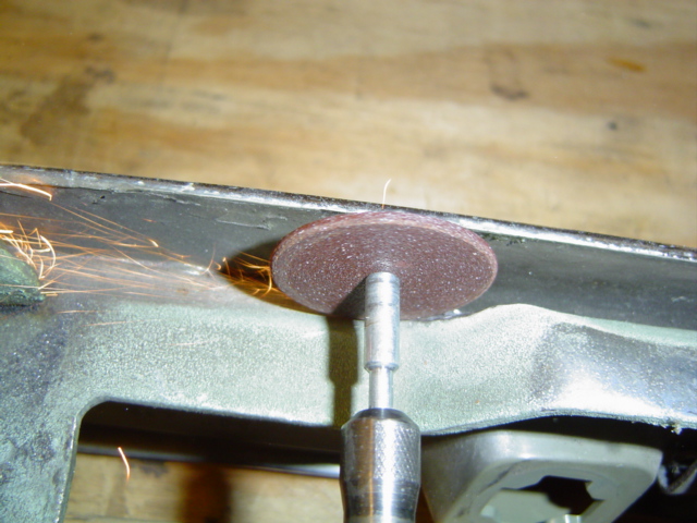
Here, I'm grinding away part of the inner bracket that was causing the interference. The bracket flared out towards the car and out towards the lip of the chrome tail fin. This was the first place where extra clearance was required.
If I ever meet the guy (or gal) who invented the Dremel they're going to get a big old pat on the back from me.
Once you start collecting different attachments, tips, stones and wheels, there isn't anything you can't tackle... within reason of course. I wouldn't cut out a whole quarter panel with the thing, but for tight quarters they're hard to beat.
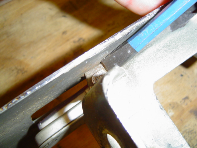
Then I attended to the one place where a weld was causing interference and I couldn't get to it with Mr. Dremel. This meant I had to go after it old-school style with a hammer and chisel. This worked okay to remove enough of the weld to gain the clearance I needed.
If the diameter of my cut-off wheel had been an inch or so bigger I could have used it. Not wanting to waste time going off in search of another tool, I simply made do with what I had on hand at the moment.
I attempted to use a couple of the real thin/narrow grinding stones I had, but the first came detached from the shaft, and since I didn't want to completely destroy my last one, I stopped.
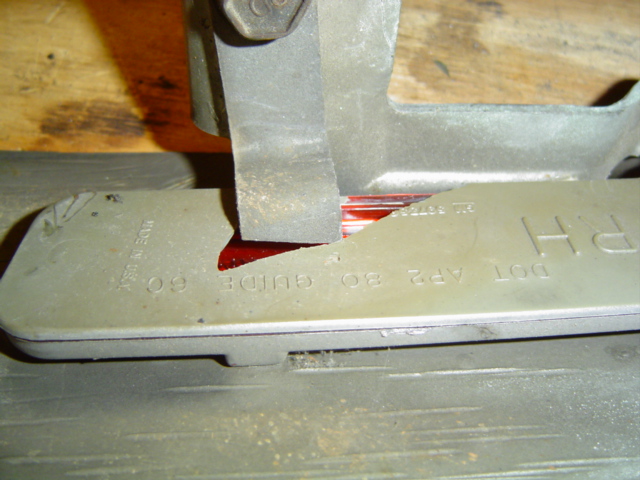
Here's one reason why I prefer the Dremel over the chisel. Unbeknownst to me, as I wailed away above with my chisel, I neglected to look to see what might be in the vicinity that might not take too kindly to such bashing about.
Guess what? Yep, the side marker light was mounted on the opposite side of the bracket I was chiseling. Evidently the plastic must've gotten... oh I don't know... a bit brittle over the years.
You know, they just don't make good plastic like they used to. All joking aside, I only had one piece that I had to melt back together with my improvised plastic welding device (aka soldering gun w/smoothing tip).
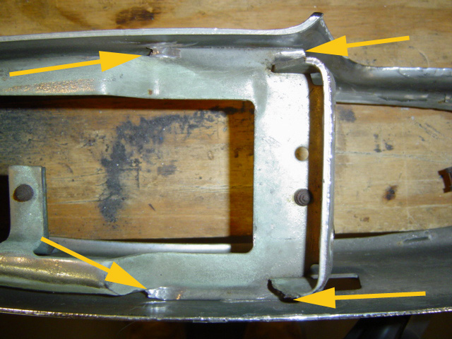
Okay, so let's say you're smart enough to remove the side marker light before embarking on your modifications. The aftermarket parts I used required modifying the factory pieces in four locations as seen here. The two welds (to the right) attach the mounting bracket.
The two locations to the left are where the bracket flared out towards the outside edge, causing the other interference I had to deal with. This was due to the extra width of the aftermarket pieces and the material was thicker at this point as well.
For some strange reason whenever I get close to the end of a given project, the last item to be worked on gives me the biggest headache. This project was no different.

Finally after much finagling around, I was able to get the passenger side tail fin mounted. The gap or ridge is a bit uneven as the fin rises up from the bumper, but fixing that would entail bending the mounting bracket.
Since the fit is the same as the original, that's one can of worms I'm not going to touch. The fit and finish is as good now as when it rolled into my yard.
Once again, if you look closely you can see the little silver button, all that's visible of the aluminum post/screw fastener I used on each side to pull the filler panel into position. Most of the force is being applied by the chrome tail fin, this is just a little extra support.
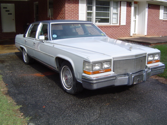
So here we are. Just a hair over one year to the day she rolled in. The first thing I had to do was roll it out so I could wash off all the dust and dirt that inevitably accumulates over time. Even partially protected by a carport can't keep all the dust off a car that's not driven on a daily basis.
I only hit one minor snag when I started her up. Seems there was this one last valve cover bolt that had somehow never been tightened. Driver's side, bottom edge, by the firewall of course.
I snapped a few 1/4 inch extensions together, threaded it past the power brake booster and sure enough that last bolt was loose as a goose. I tightened it, checked the rest, problem solved.
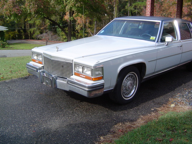
A shot of the driver's side. Hard to notice all that's been accomplished, but I guess that's to be expected since the goal was to make the car look original once again.
I do think that taking a little extra time to sand and polish the cornering lamps only ads to the effect. The smooth, clear surface only helps to set off all the other details I've worked on.
At least this helps to illustrate how all the little things come together to create a finished, detailed appearance. Granted, she still needs to be polished and waxed at this point, but already looking a million times better just having been washed.
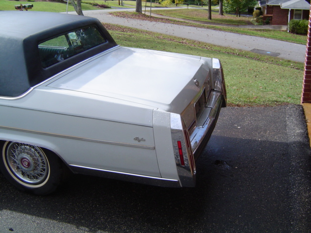
So, how did the tail fin filler pieces turn out? Judge for yourself. The only flaw is the fact that the pinstripe point that was on the original filler panel is absent. I couldn't devise anything that wouldn't call more attention to this, so I left well enough alone.
If you look closely, you can probably tell that the lower rear quarter panel is a touch darker than the fin filler piece. I'll be using some white polishing compound to remove the oxidized paint, lightening it in the process.
Again, if you look closely, you can see the filler panel beneath the license plate bracket. Overall, I'm quite pleased with the results, and I'm sure Dad will be too when I do my "reveal" this coming weekend.
© Copyright 2009 Brian Petruska | Top | Upgrades | GM Performance Parts | HTML Now! | Apple | Comments |